Table of Contents
- About this manual
- Acknowledgements
- W2 System
- W2 wind turbine
- W2 turbine controller
- Morningstar controllers
- Diversion loads
- Batteries
- Inverter
- PV modules
- System software
- System operation
- Troubleshooting
- DocBook
This manual is a catch-all document describing how the W2 System was developed and tested and how it's still evolving. It serves as a User Guide, Installation Manual, Operating Manual, and Technical Manual all-in-one – sort of like a lab notebook with bits of history, unresolved questions, possible problems, potential solutions, and random comments. DocBook was chosen as a documentation system in order to make the manual easily updatable as the W2 System evolves.
Clicking on any link in this document will take you either to the relevant manual section or to an external URL. If the latter, you may want to open the external link in a separate tab. On a Mac, use +click. On a Windows PC, use +click.
Note
This is a NOTE – Helpful information. Background information. Unresolved questions. Possible problems and potential solutions. Comments that don't fit elsewhere.
Tip
This is a TIP – Advice from actual experience. Maintainance advice. Decommissioning advice.
Important
This is IMPORTANT – but not really a Warning or Caution.
Caution
This is a CAUTION – about potential damage to equipment.
Warning
This is a WARNING – about potential physical danger to people.
The W2 wind turbine is a component of the W2 System. Both are the result of years of work by a small group of dedicated people. A great part of the day-to-day work was accomplished by Jeb Mead (design and machining), Elliott Ryan (design and marketing), and Suzanne McMannis (grant administration and bookkeeping). Enormous contributions of time and effort from Chuck Wright (electrical engineering), Keith Epstein (mechanical engineering), Jeff Minnema (aeroelastic modeling and blade design) and Brad Sykes (blade fabrication) were indispensable to the final product. Unremitting encouragement also came from Phil Hofmeyer (formerly Associate Professor, Morrisville State College) and Rebecca Barthelmie (Cornell University).
And finally... WWE is indebted (literally) to NYSERDA for providing a product development grant that got us most of the way there in about four years time.
 |
Note
Weaver Wind Energy is not currently in business. However, it could come alive again if product interest, funding, and social circumstances allow. This documentation is an effort to make a restart easier and to preserve some of the company's knowledge and experience. In fact, there may be sufficient information here to get a good start on re-creation of the W2 turbine and W2 System from scratch. Feel free to contact me with questions or proposals.
The W2 turbine was designed primarily with Quality in mind, not profit. While this is anathema to most capitalists, the world is quickly changing. I believe that small-scale wind energy can play a role in an equitable society where caretaking of – not profiting from – either the natural world or our fellow humans is our first priority. Working together, with Nature and with each other, we might accomplish anything.
Weaver Wind Energy
PO Box 1
Tres Piedras NM 87577
+1.607.379.3678
arthur.jensen.weaver@gmail.com
Last updated: 07/23/2025
The W2 System is a flexible, integrated system of small-scale wind and solar hardware designed around the W2 wind turbine, W2 turbine controller, and battery-based energy storage.
While the W2 wind turbine is intended to be the primary energy-producing component of the W2 System, PV modules, hydro, or any other source that can be interfaced with Morningstar controllers can easily be integrated into the system. The W2 turbine controller has been designed with an extensive real-time interface to Morningstar, Nuvation Energy, and Outback Power Systems components.
Real-time data from all components in the basic W2 System – W2 turbine controller, Morningstar controllers, Nuvation Low-Voltage BMS, Outback Radian-series Inverter – are routed to a Data server and presented in a dashboard-type format on a detailed System monitor web page web page.
Note
Background: Starting around 2010, simple grid-connected inverters (not requiring batteries) for small wind turbines were becoming unavailable in U.S. and Canadian markets. This was apparently due to declining consumer interest in small wind along with dramatically decreasing costs for grid-connected solar. As a consequence, WWE decided that development of a small wind system around battery-based, grid-interactive inverters was necessary for business viability. From about 2017, lithium ion energy storage began to become more available and affordable, and consumer interest in off-grid systems was increasing. These factors led to the development of the W2 System. In addition to creating the W2 wind turbine and W2 turbine controller, WWE focused on integration of “off-the-shelf” components (lithium ion batteries, battery charge controllers, battery management systems, and inverters) with the W2 turbine and controller. This “hybrid system” approach seemed like a good way to encourage adoption of an innovative wind turbine tightly merged with commercially proven system components.
Important
Site selection for a wind turbine tower involves many considerations which may impact decision-making about project viability. It is important to understand: 1) that the labor and materials costs for a suitable tower typically amount to more than 50% of total investment in a small wind project, and 2) that acquiring necessary permits for a wind turbine tower may, for many reasons, be next to impossible in many jurisdictions. Whether or not a wind tower installation is affordable and allowable may well be the *determining factors* in choosing the W2 System. Please refer to the section on Towers for more discussion.
Apart from decisions about Towers, the first step in W2 System installation is choosing an indoor location for the Inverter and Batteries. They should be placed close to one another to avoid cable lengths over 10-feet or so between them. The inverter location is often chosen to be near an existing (usually the main) electrical service panel.
 |
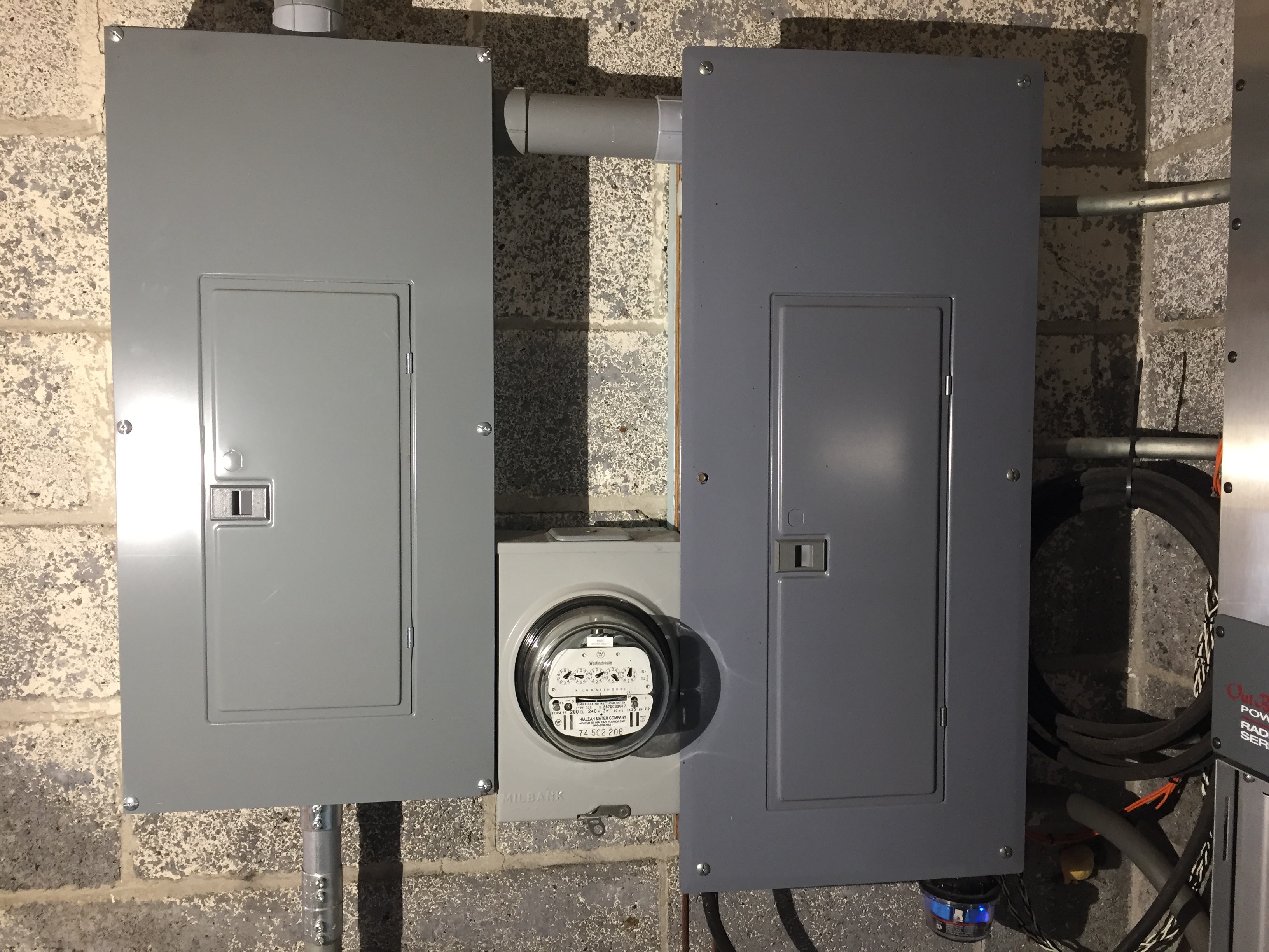
A “backup” loads panel, supplied by both the inverter and grid via a manual or automatic transfer switch, will typically need to be installed adjacent to the existing service panel. In the photo below, the main service panel on the right is joined by a conduit stub at the top to a backup loads panel on the left; an Outback Radian-series Inverter is just visible at the far right.
 |
Tip
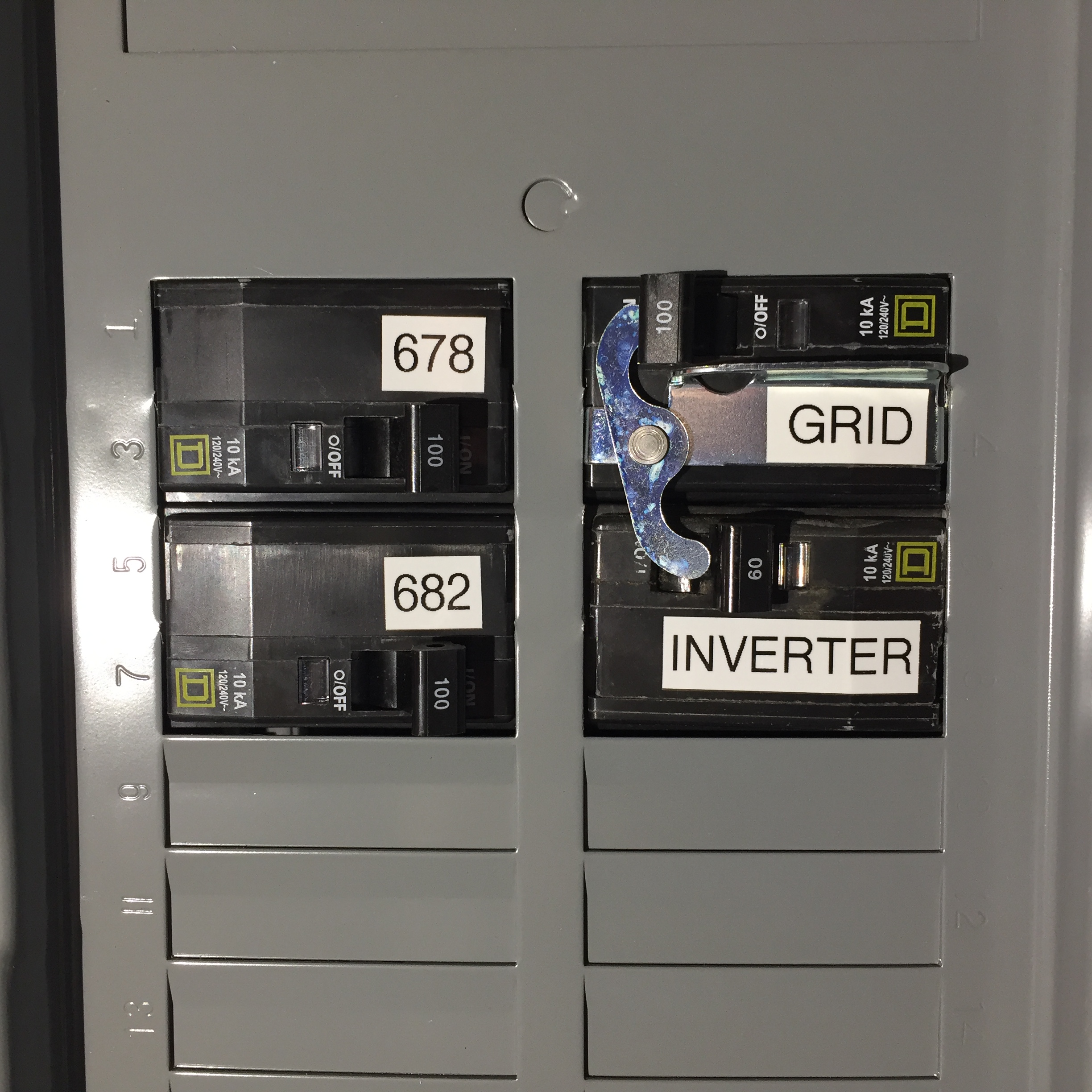
Because inverter(s) are often undersized (due to cost) relative to maximum possible power consumption and because an automatic transfer switch can switch so quickly as to be unnoticeable, we strongly recommend using a simple manual transfer switch to avoid unintentional overloading of the inverter(s) and/or unintentional drawdown of battery capacity when electrical outages occur. The photo below shows a simple circuit breaker accessory functioning as a manual transfer switch inside the backup loads panel of the above photo. This panel supplies either grid (100A/2P breaker) or inverter power (60A/2P breaker) to two adjacent dwellings (labeled “678” and “682”) where each is supplied by a 100A/2P breaker.
 |
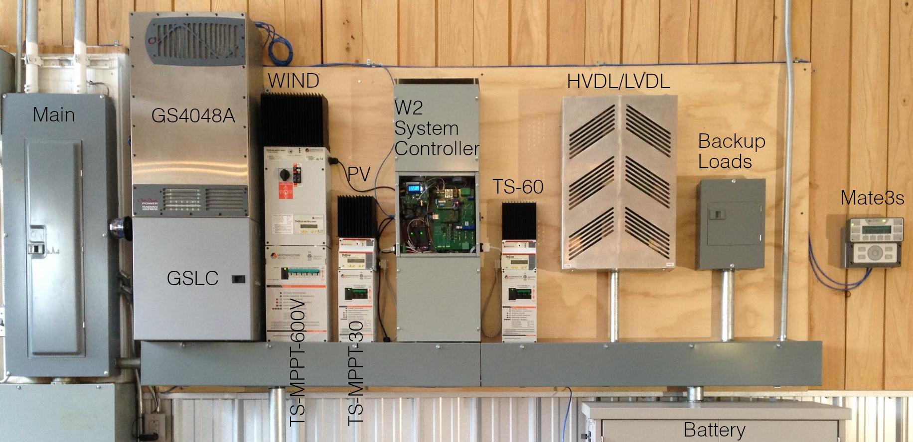
The W2 turbine controller and Morningstar controllers (TS-...) are typically installed close to the Outback Radian-series Inverter (GS4048A or GS8048A) to allow easy routing of power conductors to DC busbars inside the load center (GSLC). One method of accomplishing this is to install a wiring trough (for ease of installation we recommend 6-inch square) either below or immediately adjacent to the GSLC. The wireway should be of sufficient length to accommodate system components with necessary clearances. In the photo below, the wiring trough also accommodates the diversion loads (HVDL/LVDL) and a small (demonstration) backup loads panel immediately above the battery enclosure. Obviously, diverse system layouts are possible.
 |
This section contains descriptions of Turbine components, Turbine installation, and options for Towers.
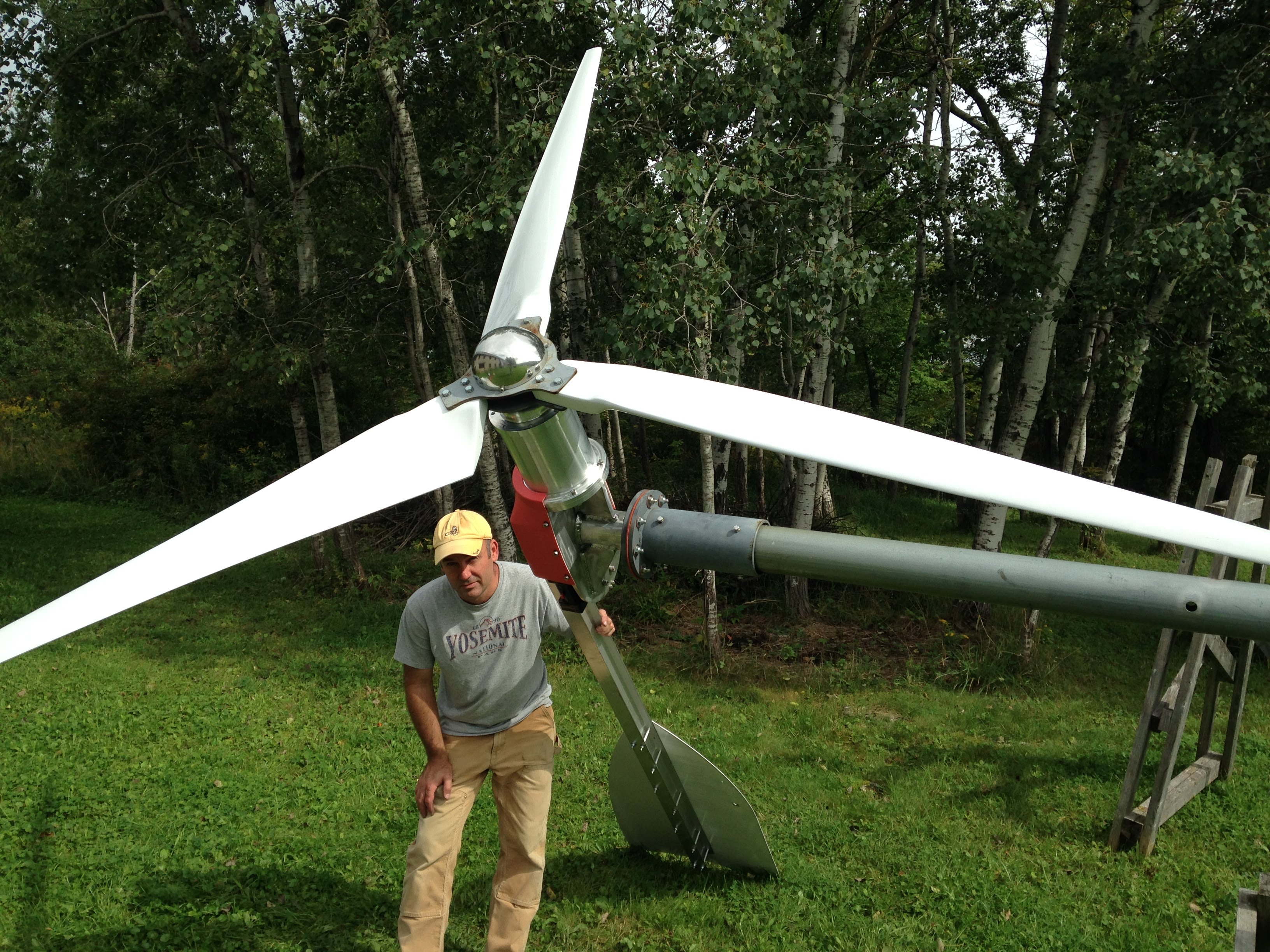 |
This section presents an overview of the mechanical and electrical components of the W2 turbine. It is intended to give some familiarity with how the turbine is put together and how it functions. After reading this section, the Turbine installation instructions which follow should be easy to understand.
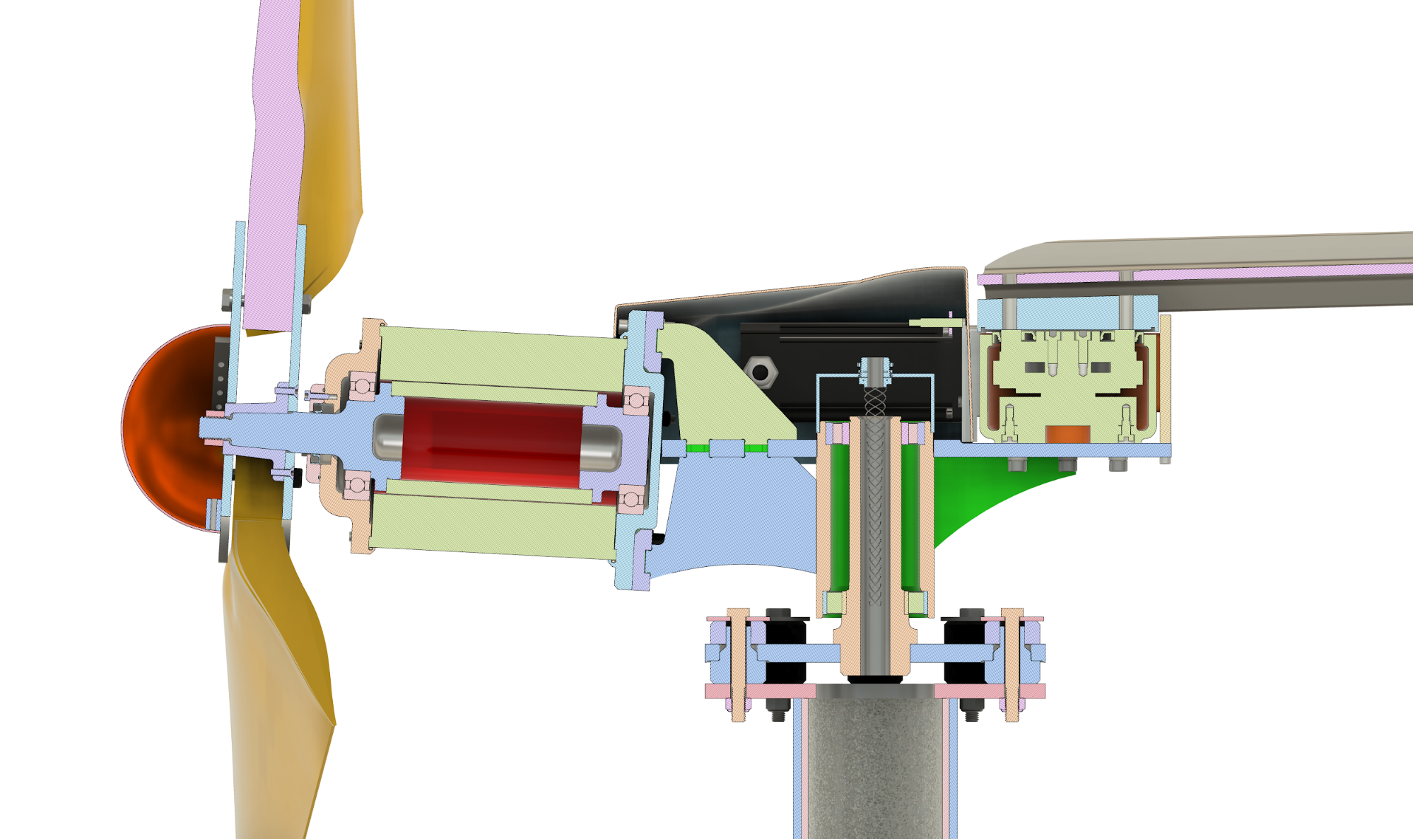
The W2 turbine is designed around the concept of active furling – where the tail angle is actively controlled in real-time to set the angle of the rotor with respect to the wind. To accomplish this, the turbine Tail assembly is directly connected through a tail coupling plate to a slewing drive and stepper motor (see Frame components). The turbine frame rotates passively on sealed bearings supported by the Yaw assembly. The Hub assembly and composite carbon fiber Blades are attached to the weather-sealed W2 Alternator which is mounted on the exterior of the nacelle frame. A few Other turbine components complete the W2 turbine description.
Note
Active furling was first conceived and demonstrated to work in an earlier WWE turbine – the W5. This turbine was larger (5kW) with a design which allowed for only two tail positions – fully extended or fully furled. Intermediate tail positions could not be maintained accurately, even for short periods, due to back-sliding of the linear actuator (ball screw) mechanism used for tail movement. The consequence of this was a significant loss of turbine energy production due to the relatively slow transition time (several seconds) between the two tail states.
In contrast, the W2 turbine employs a slewing drive which essentially locks the tail at whatever position it is driven to. This simple innovation allowed the development of a real-time partial furling algorithm realized in Controller firmware which greatly improves energy production. Because it was initially unknown whether a slewing mechanism with a sufficiently fast response time could be produced, R & D was done on a smaller scale than the W5 – primarly to reduce costs.
The Alxion 190STK4M alternator is supplied from the manufacturer as a two piece “frameless” rotor and stator to which a customized weather-tight “frame” (rotor extensions, bearings, end plates, seals) appropriate for a small wind turbine have been added by WWE. The rotor is bolted to a one-piece stainless steel square tapered shaft (which mates to the Hub assembly) at one end, and to a shorter stainless steel support at the other end (see photo).
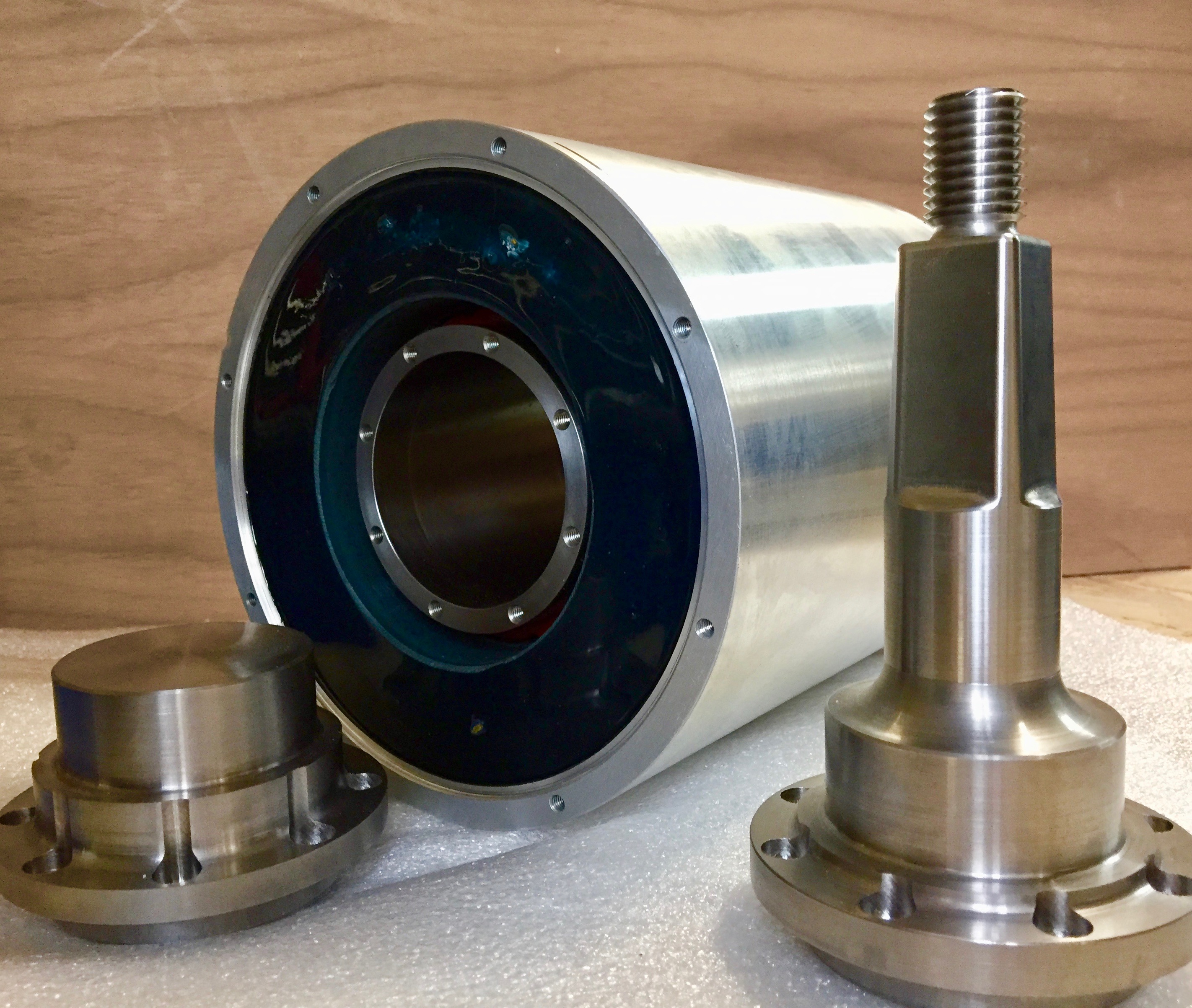 |
The stator has a cylindrical aluminum housing to which front and rear aluminum end plates (shown in the photo below) are bolted. A sealed SKF bearing is press-fitted onto the front rotor extension, and a shielded SKF bearing is press-fitted onto the rear extension. The bearings are supported by their respective end plates.
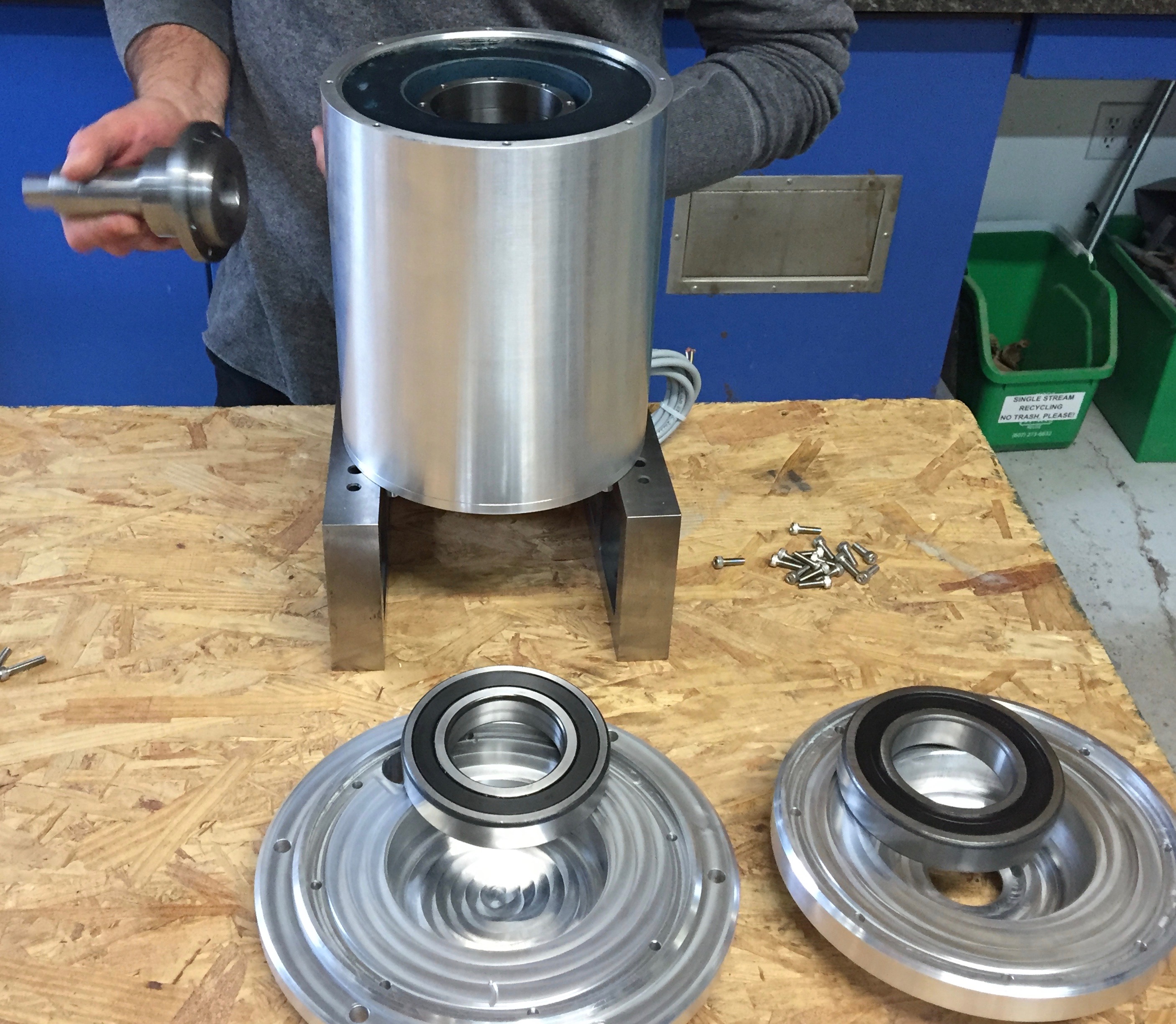 |
An external alternator shaft seal, designed to be field-replaceable, completes the assembled alternator which is bolted to the Turbine frame.
 |
Note
The Alxion alternator was selected because it gave WWE the ability to develop a finished product that was truly engineered as a small wind turbine – with bearings and seals appropriate to an extremely demanding application. Prior to this, we field tested other “finished” alternators, all of which began to deteriorate after 2 to 3 years. Further, because WWE designed the alternator frame, we have the ability to refine and improve the design with time and field experience. Alternator refurbishment and repair also becomes possible.
Caution
A damaged W2 alternator may be repairable because its design allows for relatively easy disassembly. However, this should be undertaken only with appropriate tooling and safety precautions. Specifically, the very strong NdFeB permanent magnets inside the alternator create hazards which inexperienced persons may not anticipate. Please contact WWE for further guidance.
Tip
Decommissioning: An irretrievably damaged alternator can be recycled without requiring disassembly. Metals recyclers will typically classify it as an “electric motor”.
Airfoil design for the W2 blades and aeroelastic simulation of W2 turbine was carried out by Jeff Minnema Consulting. The composite carbon fiber blades were manufactured for WWE by Brad Sykes Design. The blades are secured in the Hub assembly. Rotor radius from hub center to blade tip is 57.5 inches.
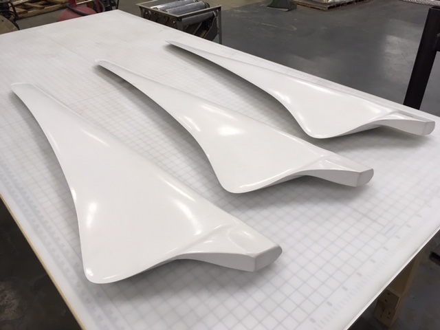 |
Note
High quality “off-the-shelf” or OEM blades for small-scale wind turbines are essentially non-existent, so WWE had no option but to develop custom blades for the W2 turbine. The end result is an ultra-light, carbon fiber blade with aerodynamic characteristics that discourage rotor overspeed in high winds. Because the blades are custom-made in small batches with extensive labor, they are costly. A far less costly alternative, which we consider viable, might be to manufacture wooden blades with a similar aerodynamic profile. The tradeoff would come in required blade maintenance (e.g., annual surface recoating and minor repairs) and ultimately blade replacement. Importantly though, environmental impact would probably be lessened.
Tip
Decommissioning: Wind turbine blades incur damage for various reasons. In most cases, minor surface damage can be repaired on-site. More extensive damage can be addressed by returning the damaged blade set to WWE for repair and rebalancing. While recycling of composite materials currently presents a challenge, carbon fiber recycling firms such as Shocker Composites may offer a solution.
With the exception of the tower cable and strain relief, all frame components are directly bolted to or pressed into the turbine frame. The Alternator is discussed separately above.
The turbine frame is composed of several machined 6061 aluminum pieces close-fitted and then welded together (see photos and exploded diagram). The turbine frame is supported by the Yaw assembly.
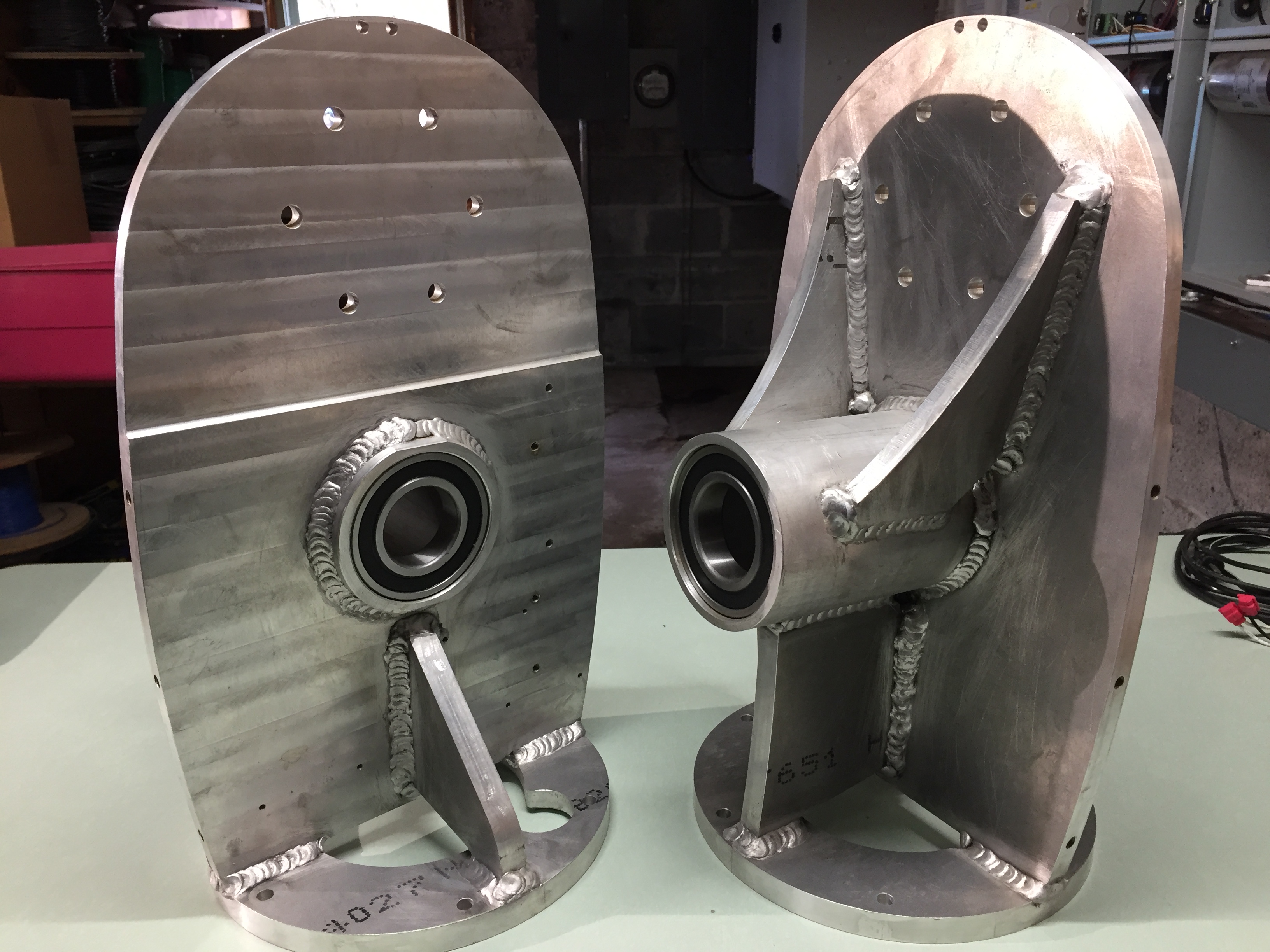 |
Sealed yaw bearings [include link to manufacturer] are pressed into the turbine frame (see photo above) which slides onto the Yaw assembly.
An Anaheim Automation 34Y65214S-CB8-03 sealed high torque stepper motor (-03 denotes a custom 12mm shaft) is coupled through a machined aluminum adapter to a Cone Drive (H-Fang) SE3C-62-12R-REV.C slewing drive which is bolted to the nacelle platform. The heavy slewing drive cantilevers the attached stepper motor slightly above the nacelle platform.
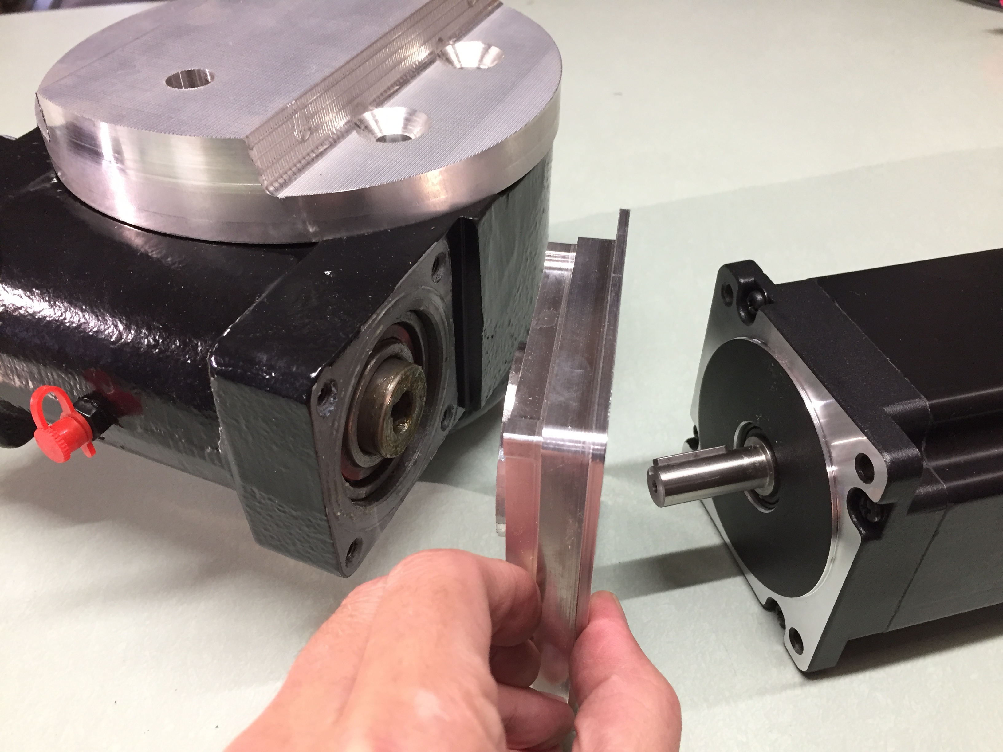 |
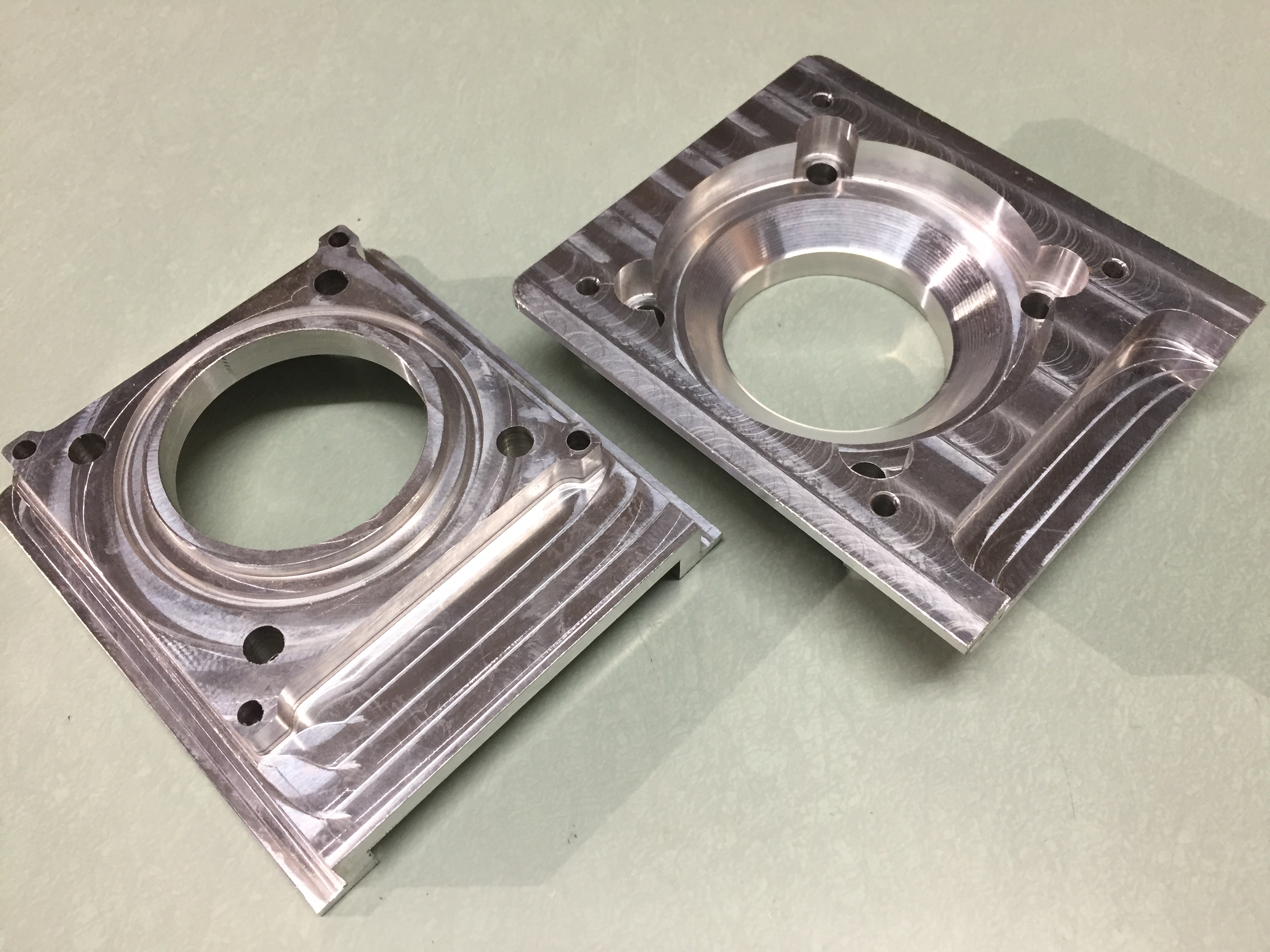 |
Tip
Maintenance: Periodic injection of silicone-lithium grease into a grease fitting (protected by the red plastic cover in the above photo) to completely fill the internal volume of the slewing drive is critical to preserving its service life. The W2 slewing drive grease should be topped off at least annually and possibly more often in challenging conditions. WWE recommends that this simple, yet critical maintenance be done every time the turbine is physically accessible for service.
The slewing drive manual gives grease specifications in Table 4, grease quantity in Table 5, and recommended lubrication frequency in Table 6. The large quantity (330-350 grams) for the 3-inch drive used in the W2 is not a typo; the worm gear threads and ring raceway are contiguous in this drive and occupy a surprisingly large internal volume. For reference, a cartridge of Mobilith SHC 460 synthetic lithium grease contains 380 grams (13.4 oz). While typical grease guns may eject 2-3 grams of grease per shot, others may eject less. This is important because we have found that new, factory-supplied drives may not be completely filled with grease and need to be topped off. When the drive is completely filled with grease, you should notice increased resistance to the force needed to inject further grease into the drive. During injection, watch for grease leakage around the adapter plate between the drive and stepper motor as shown in the photo below. Grease leakage is not harmful and demonstrates that the internal volume is full; simply wipe up the excess and check the tightness of the adapter plate socket cap screws (aka Allen bolts).
Caution
The slewing drive manual states that “the most frequent cause of failure of slewing drives is insufficient lubrication.” WWE has observed penetration of water into, and cold weather freezing up of a slewing drive which was unmaintained for a 2-3 year period. While it may be possible to recondition a slewing drive into which water has penetrated, it involves complete removal and disassembly of the drive. Regular maintenance as described above is far easier!
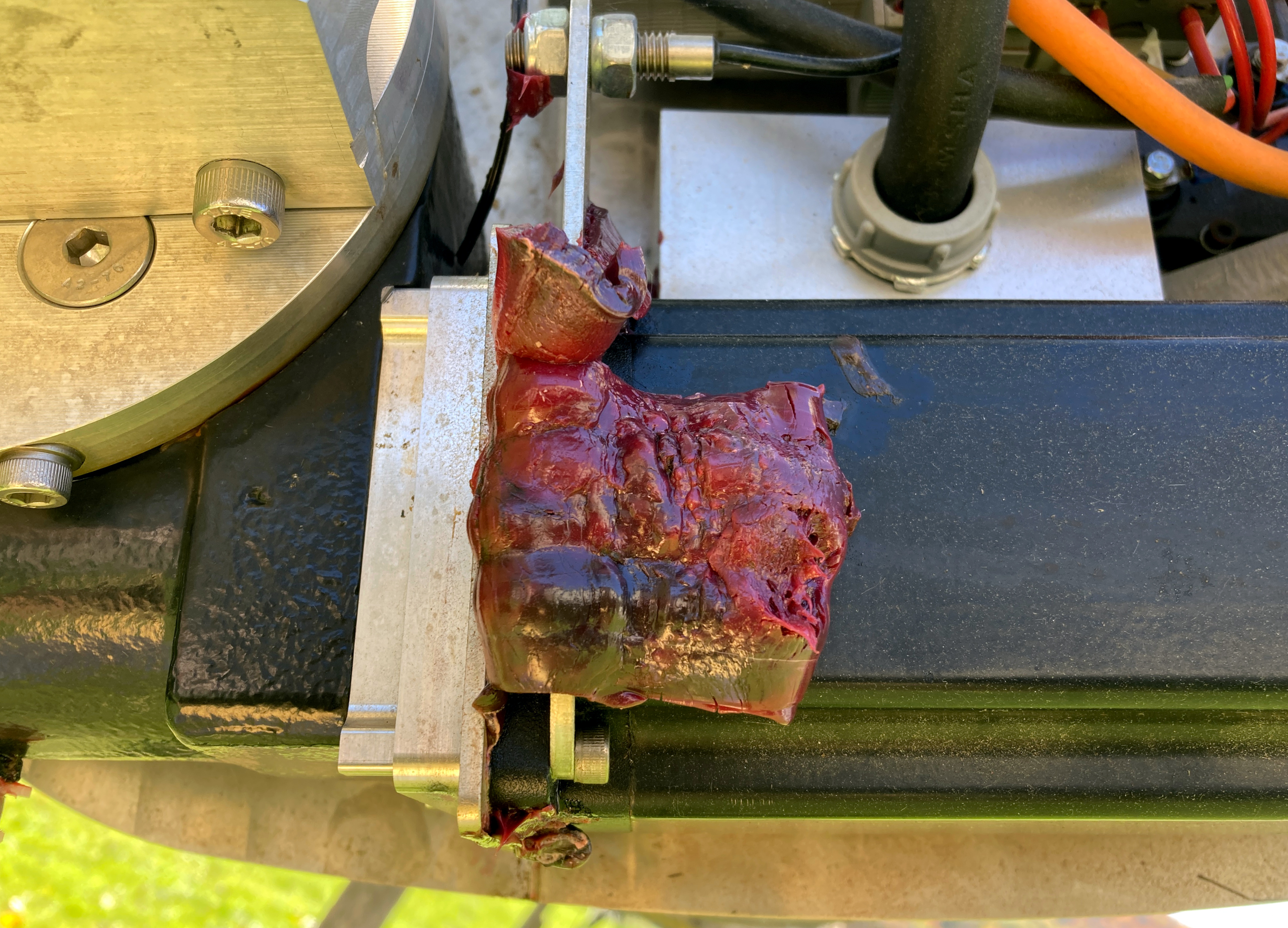 |
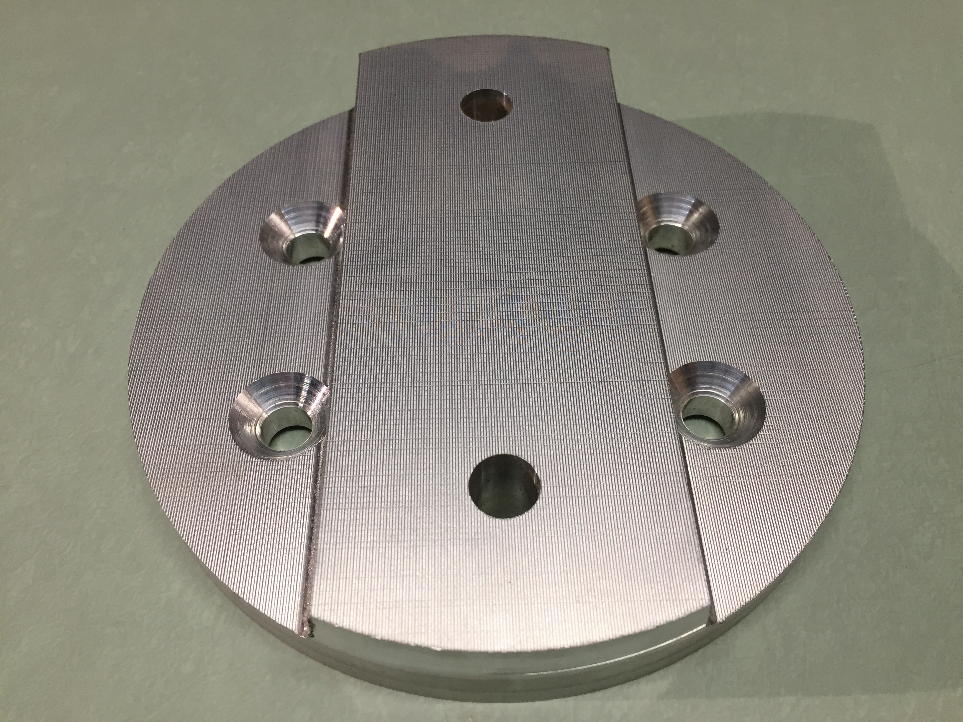
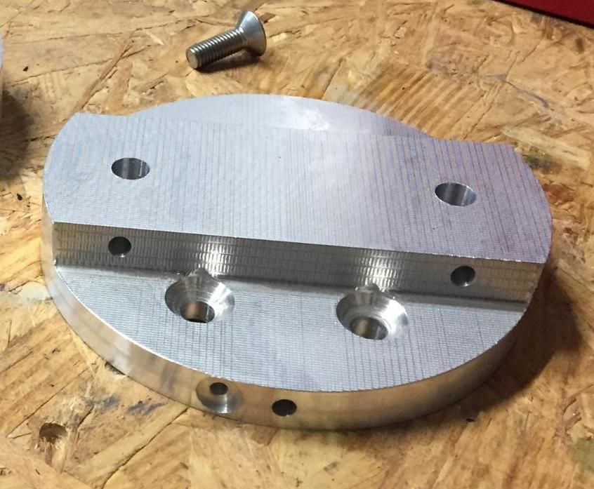
An aluminum tail coupling plate (shown in photos above and below) is bolted to the slewing drive rotor. The Tail assembly bolts to this plate which provides a 3° upward tail arm camber – see the W2 turbine cross section. Two (2) NdFeB magnets are permanently embedded with epoxy into holes in its outer rim for tail position sensing via the Reed switch. Two (2) additional recessed holes in the tail plate rim accommodate protruding bolts which physically limit tail rotation when they contact the Tail hard stop.
 |
 |
The shorting contactor is an ABB AF16-22-00-11. When DC coil voltage from the controller is lost, the 2 N.C. poles of the contactor close resulting in a short of all three alternator output leads (see electrical diagram). Put another way, the 2 N.C. poles are held open during turbine operation by an energized coil. Because the contactor coil must be energized to prevent a short, this device functions as a “failsafe” – stopping the turbine in the event of a controller fault. Other infrequent events (such as very high winds or a firmware update) will temporarily engage the shorting contactor as a safety measure.
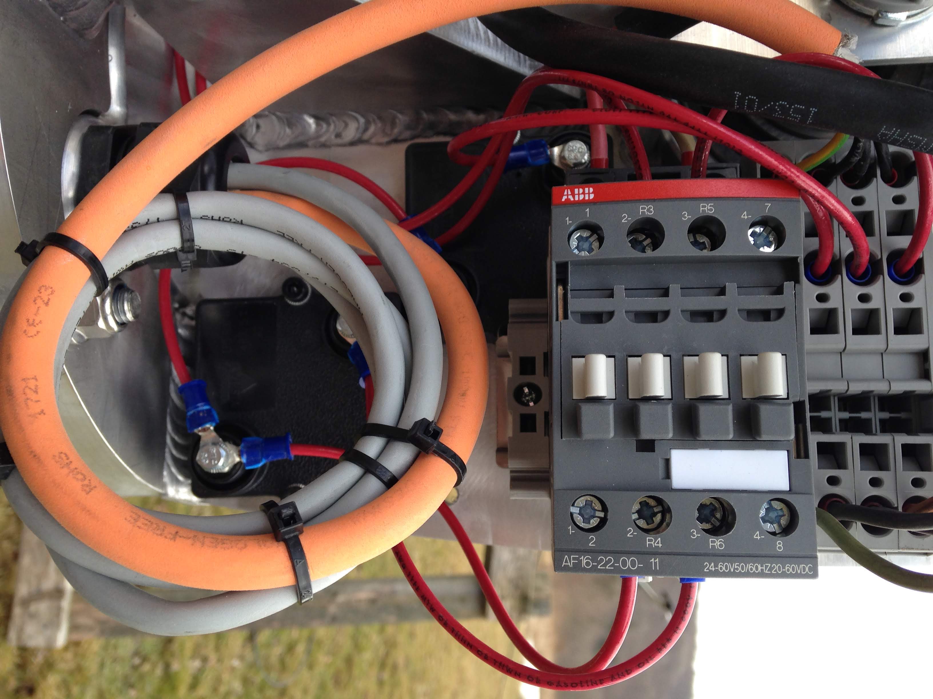 |
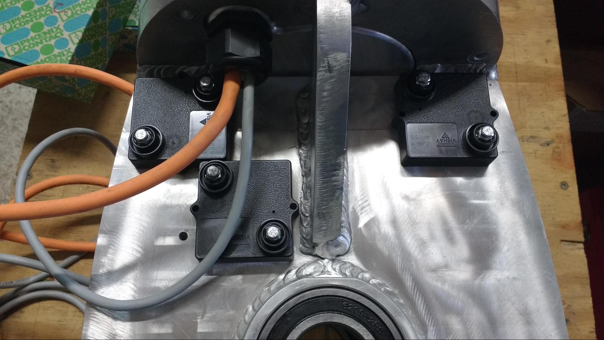
The shorting contactor shorts the alternator through a network of three (3) 4.7Ω, 600W, thick-film resistors which impart the maximum possible braking torque on the alternator at its maximum operating RPM. The photo above shows the red wires of the shorting contactor + resistor network terminating on the three (3) spring terminals of the alternator power leads (orange cable). The square power resistors are bolted to the turbine frame which acts as a heat sink. Thermally conductive pads (not visible in the photos) facilitate heat transfer between the resistors and frame.
 |
Spring terminals are used for electrical connections within the nacelle. Eight (8) 2-position terminal block connectors and four (4) 3-position terminal block connectors accept the twelve (12) tower cable conductors (see photo). In shipped units, the terminals are labeled and color-coded to match cable wire colors.
Note
WWE uses spring terminals for nacelle wiring connections because they have proved impervious to disruption due to turbine vibration. Wires are capped with ferrules to facilitate insertion into spring terminals.
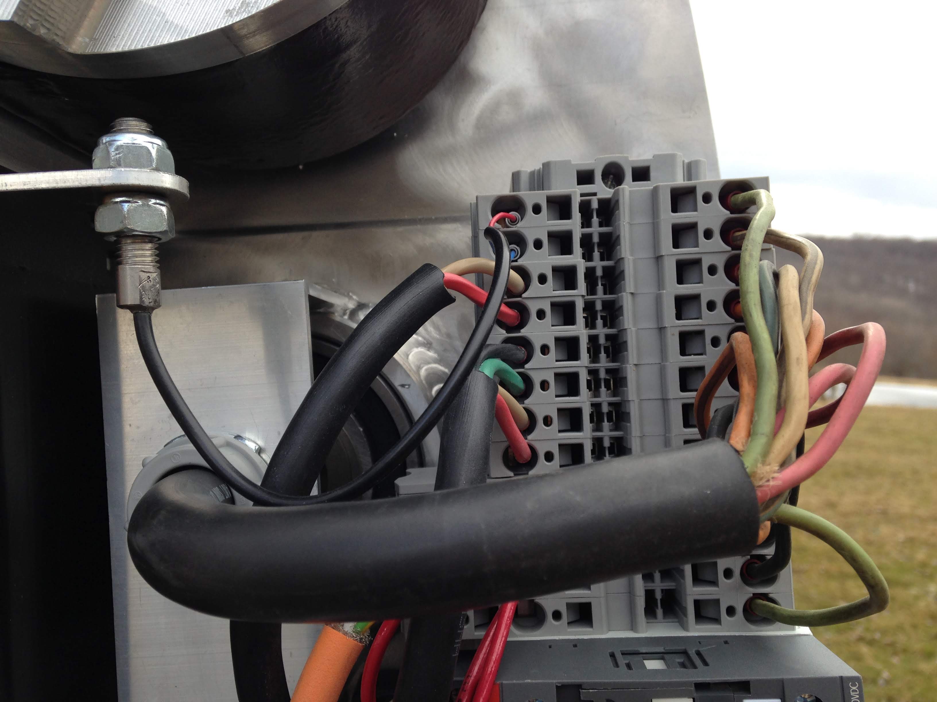 |
A stainless steel reed switch is attached to an aluminum support arm extending from the stepper motor housing (far left in the photo above). The reed switch is triggered by magnets embedded in the Tail coupling plate (just visible at upper left in the photo). The reed switch functions as a “limit switch” to constrain tail motion when the W2 turbine controller is in Auto Mode. For setup and calibration purposes, there are no tail motion constraints in Manual Mode.
The tower cable is a highly flexible, 600V-rated 16/12 SOOW cable. A 150-feet length is supplied with the turbine which will be sufficient for most towers. Strain relief is accomplished with a very simple, upside-down aluminum “U-bracket” that supports the weight of the cable with a Kellems-style grip, suspending it immediately above the yaw stem outlet. The U-bracket is threaded to accept a 3/4-inch NPT cable grip. The U-bracket is kept in place by two parallel facets milled on the top yaw bearing support and by the weight of the centered cable. For clarity, the yaw stem is not in place in the photo below.
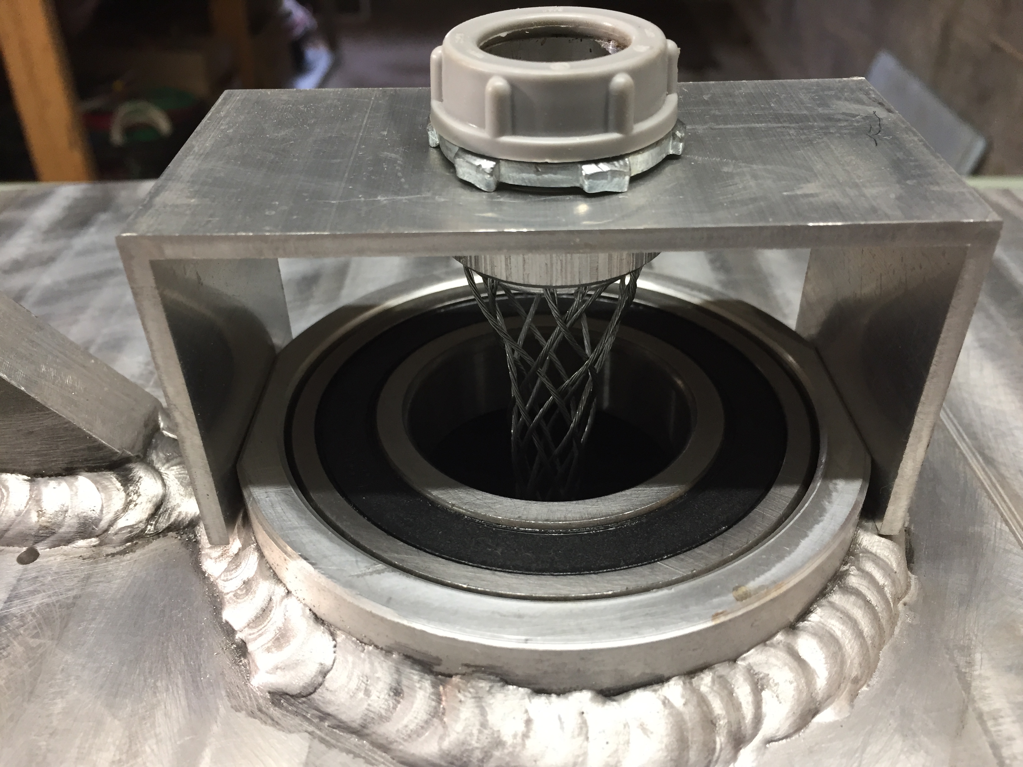 |
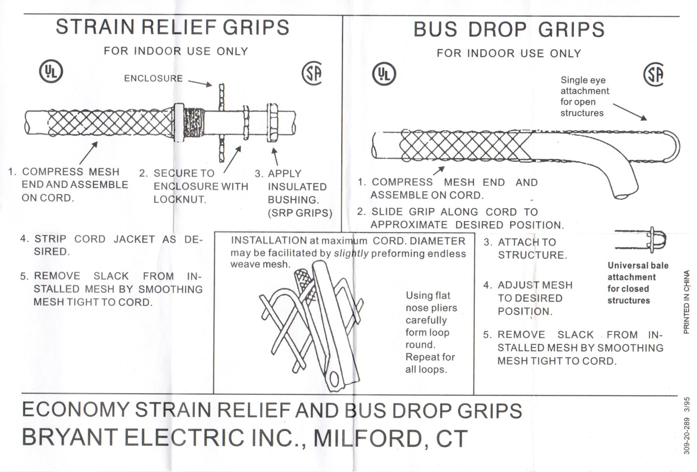 |
An aluminum post bolted to the back end of the turbine frame physically prevents tail motion beyond a point where it could interfere with the rotor. Two (2) protruding screws in the Tail coupling plate strike the hard stop if extreme tail rotation limits are reached. Stepper motor “slippage” against the resistance of the hard stop will not damage the motor (according to the manufacturer), but it will produce a loud grating sound.
Note
The hard stop is being redesigned to ensure it has sufficient strength to resist the maximum possible torque of the Stepper motor and slewing drive. The new stop will be attached to the slewing drive cover plate (square with 4 bolts in the photo below) rather than the turbine frame.
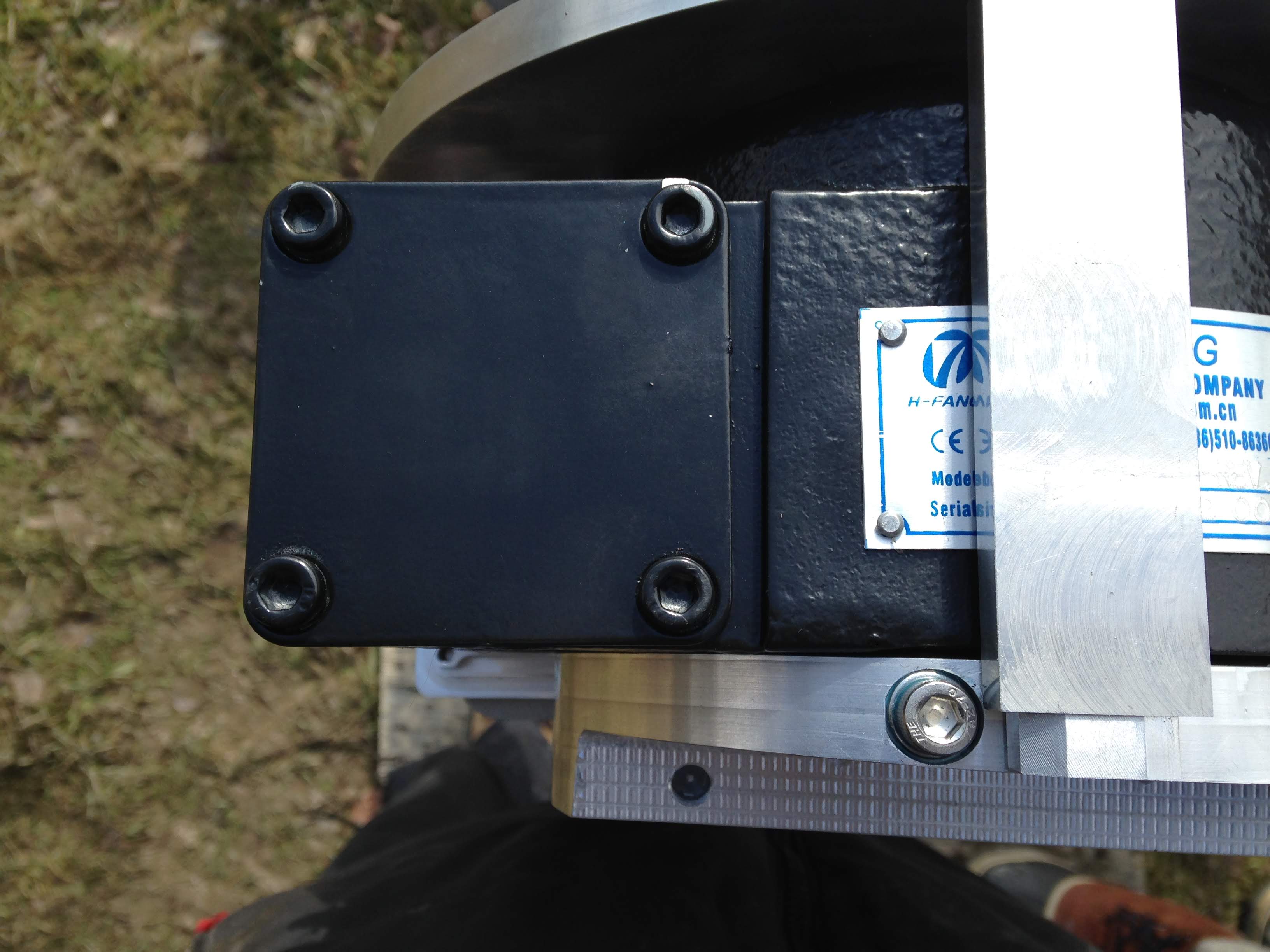 |
An initial production run of nacelle covers were 3D printed of thermoplastic and coated with a UV-resistant spray paint; the color in the photo is Cadmium Red Light Hue (510).
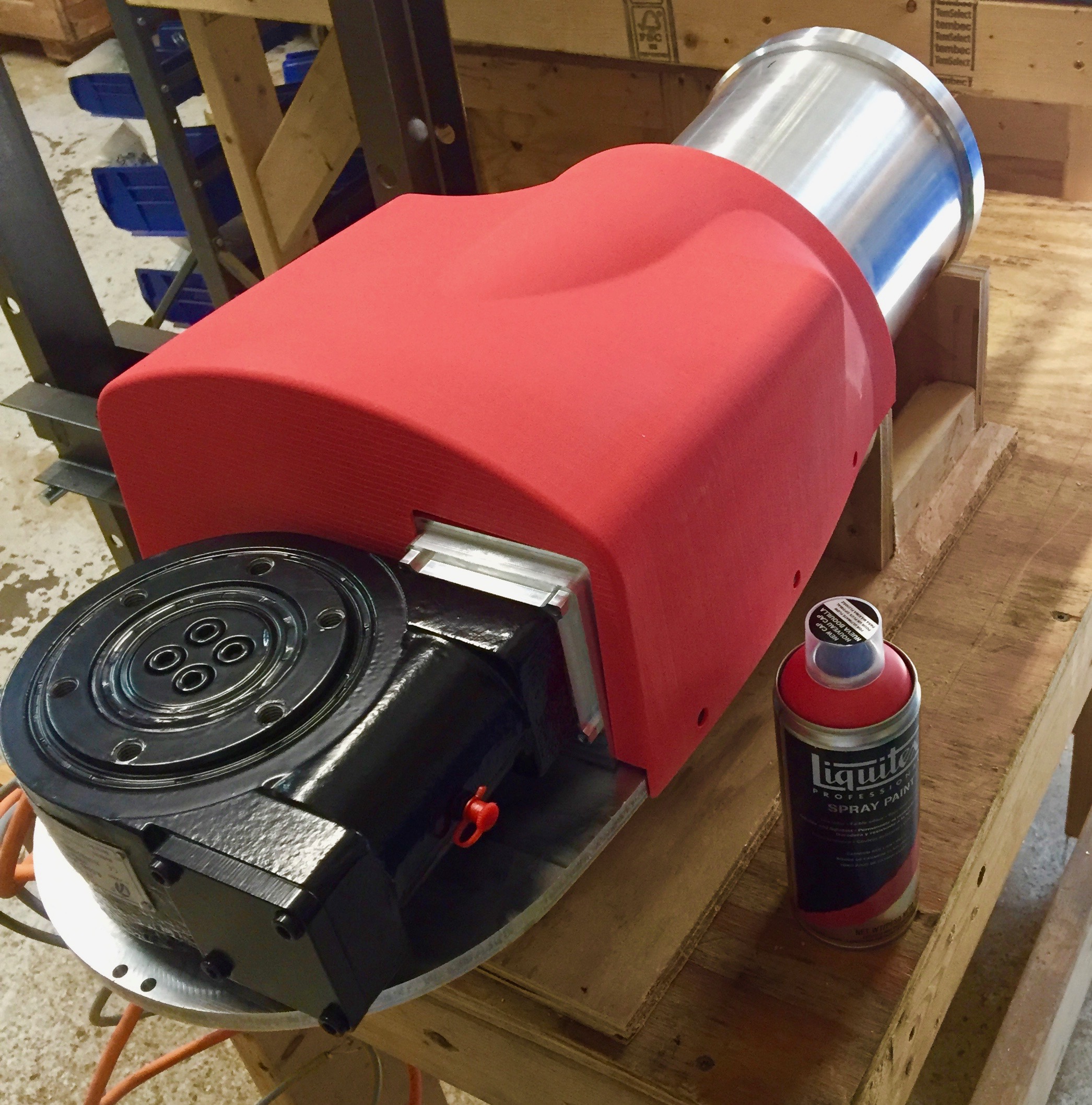 |
Six (6) bolts with rubber seals are used to attach the cover to the turbine frame.
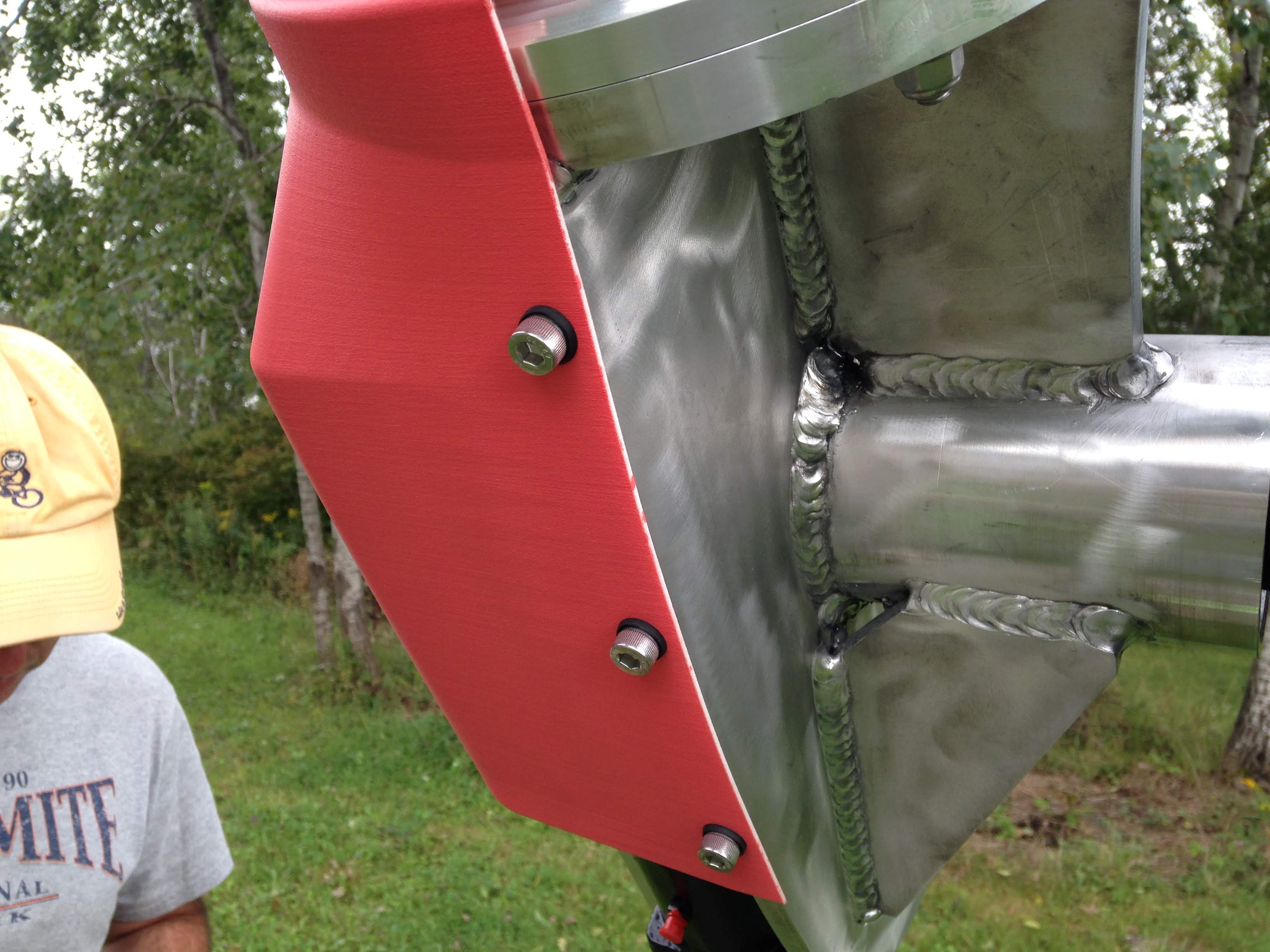 |
The coated steel yaw stem for the W2 turbine consists of a yaw shaft fitted into and welded to a wider bottom flange. A spring steel snap ring (not in place in the photo below) engages a machined groove at the top of the stem.
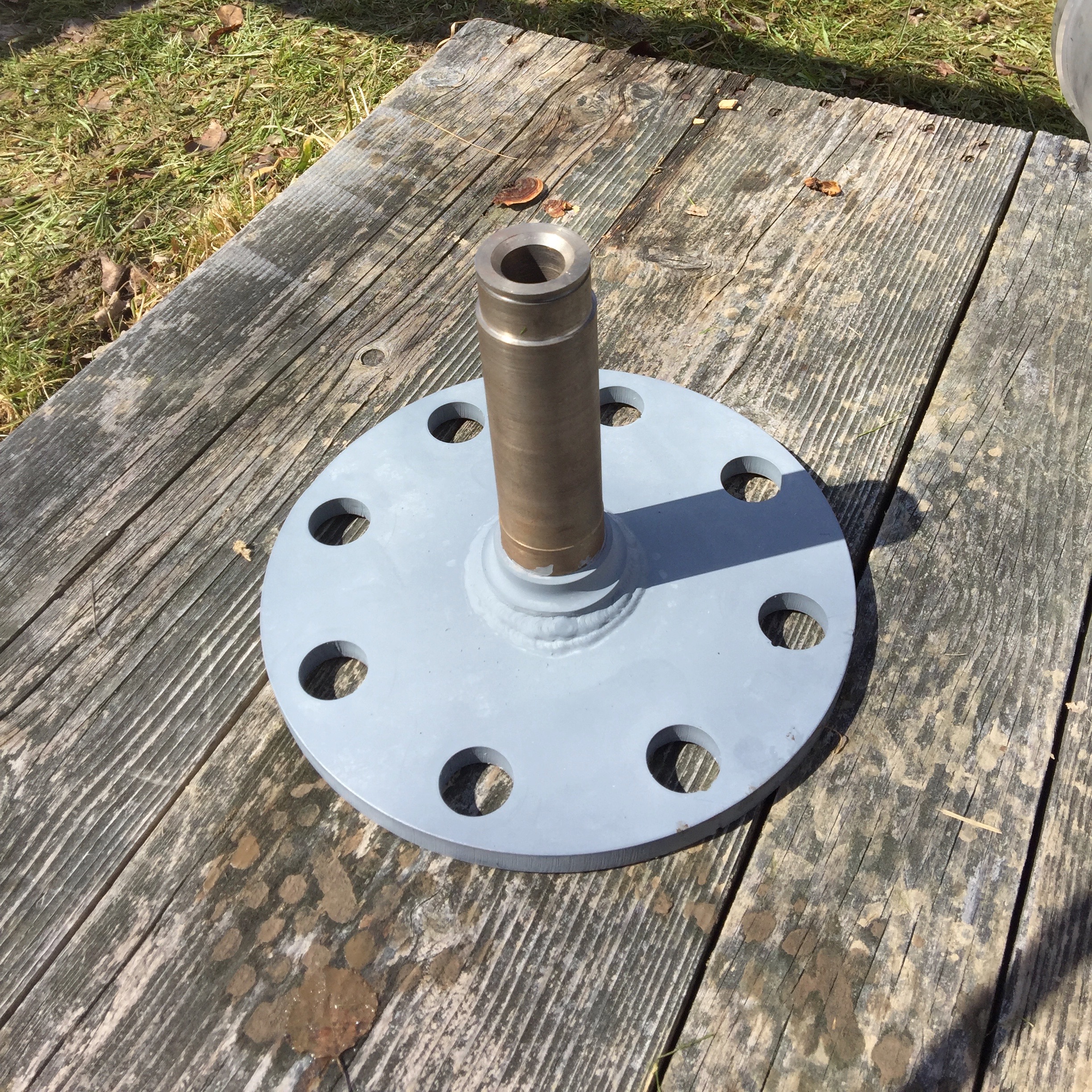 |
Vibration isolation of the yaw assembly from the tower-top flange is provided by eight (8) two-piece molded rubber mounts which sandwich the yaw stem flange, isolating it from the tower-top flange (see photo below).
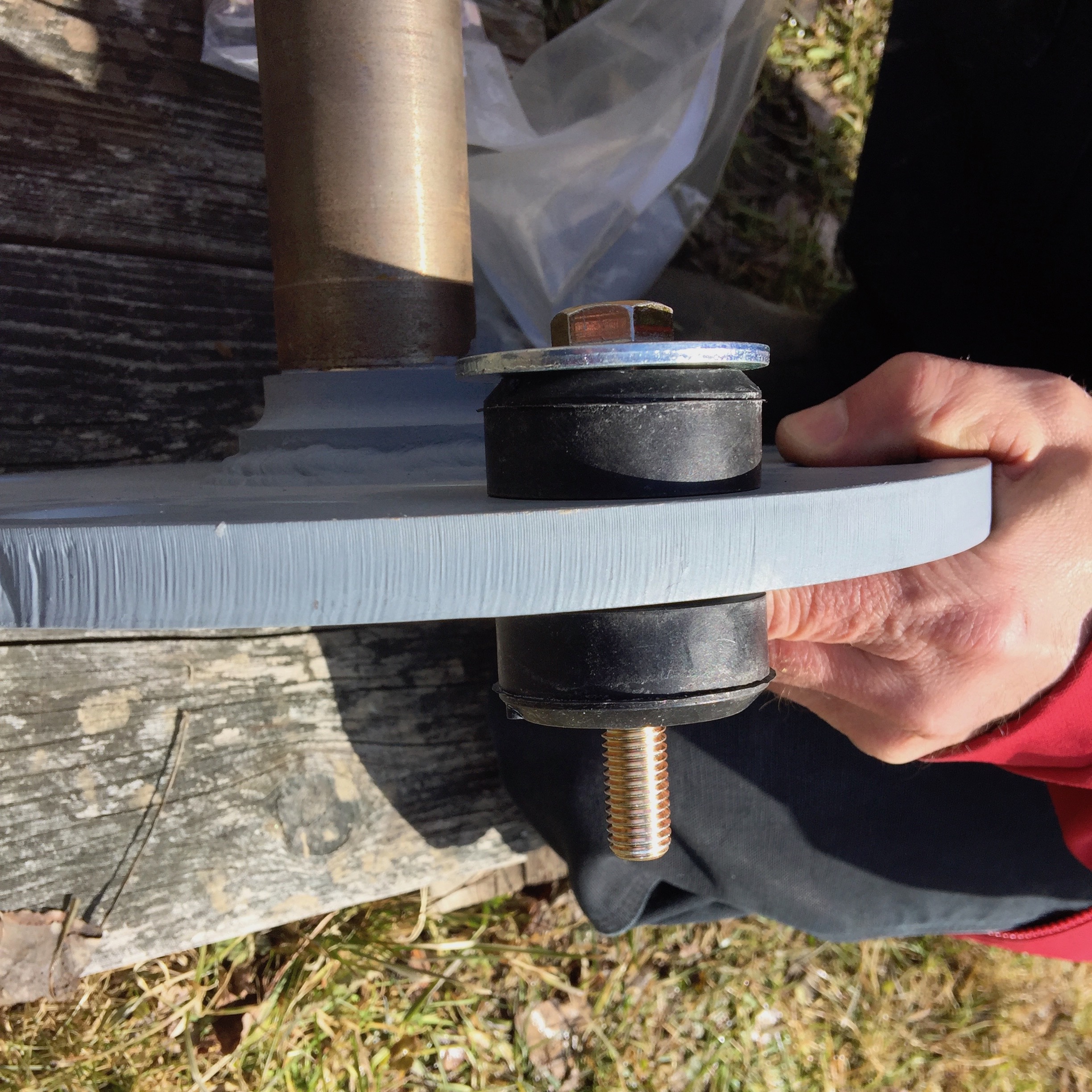 |
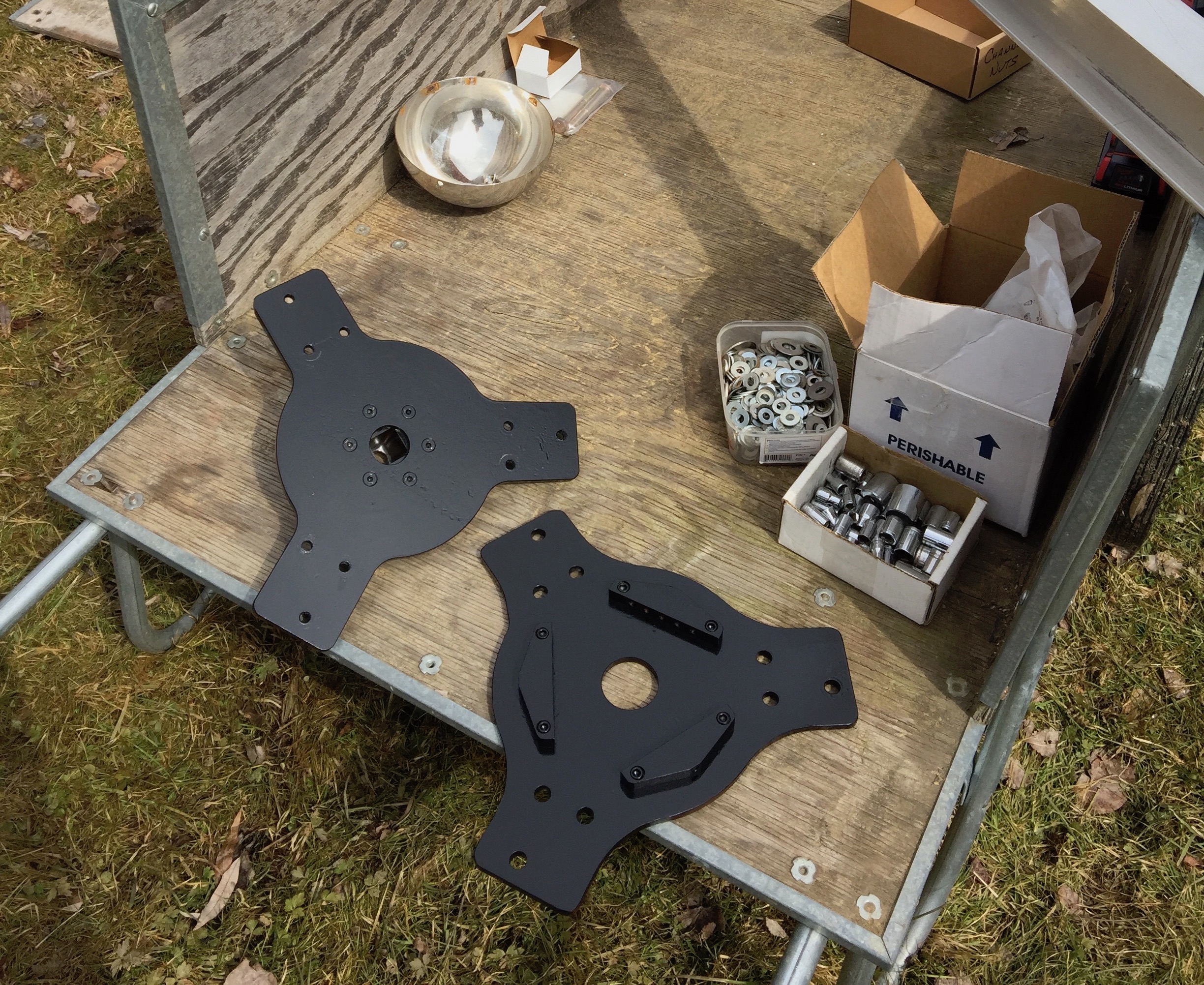
The turbine Blades are through-bolted between front and rear hub plates. A shaft collar bolts to the rear hub plate which slides onto the square tapered alternator shaft. A large Nyloc™ nut (requiring a ???-inch socket) secures the fitted rotor assembly to the shaft. Three (3) nose cone supports bolted to the front hub plate secure a pre-drilled nose cone (an 18 cm Ř stainless steel hemispherical bowl).
 |
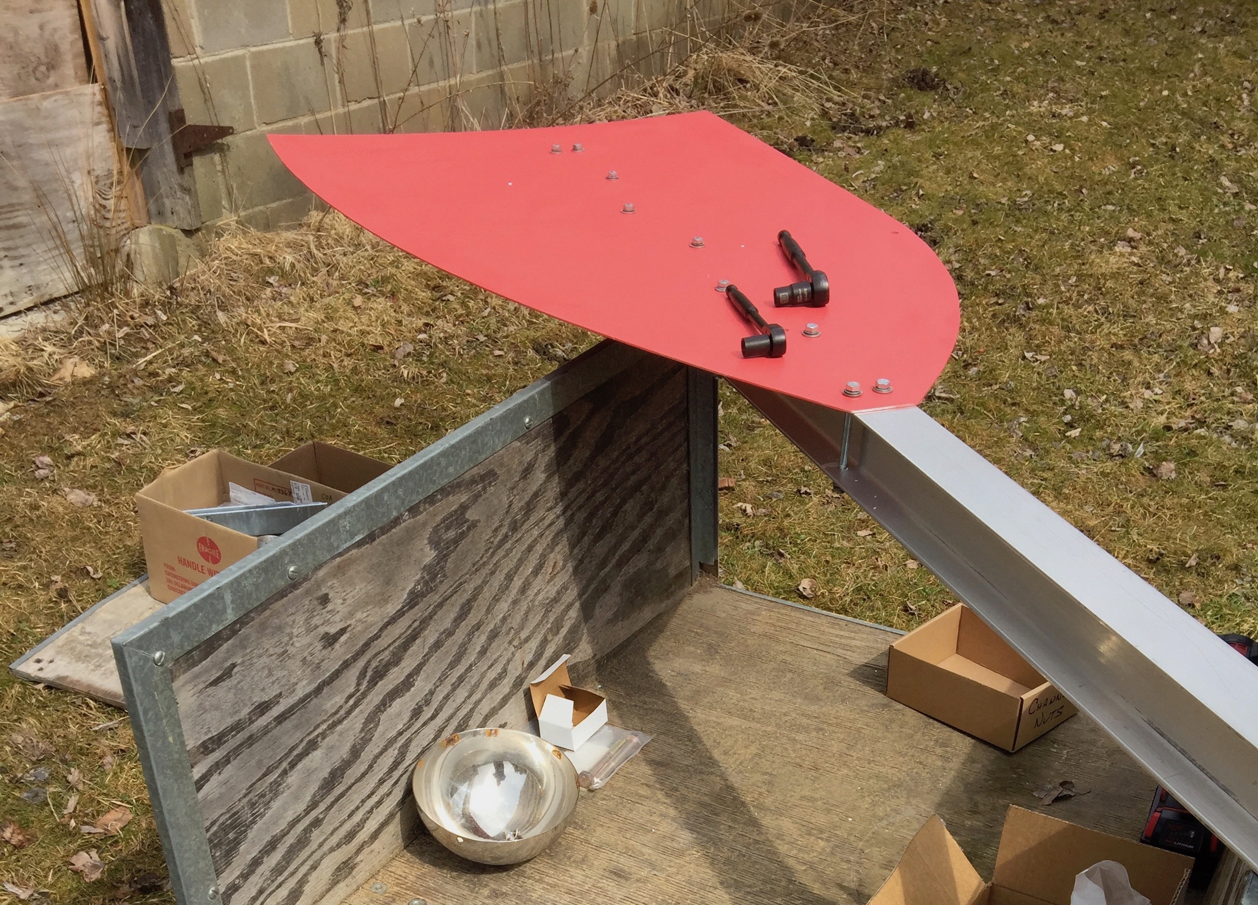
The tail assembly is composed of an aluminum I-beam “tail arm” bolted to a painted sheet aluminum “tail vane”.
Note
Painting the aluminum tail vane (any color!) was found to be necessary to avoid reflective glare on sunny days. The color in the photo is Cadmium Red Light Hue (510).
 |
The tail assembly bolts to a Tail coupling plate as shown in the photo below.
 |
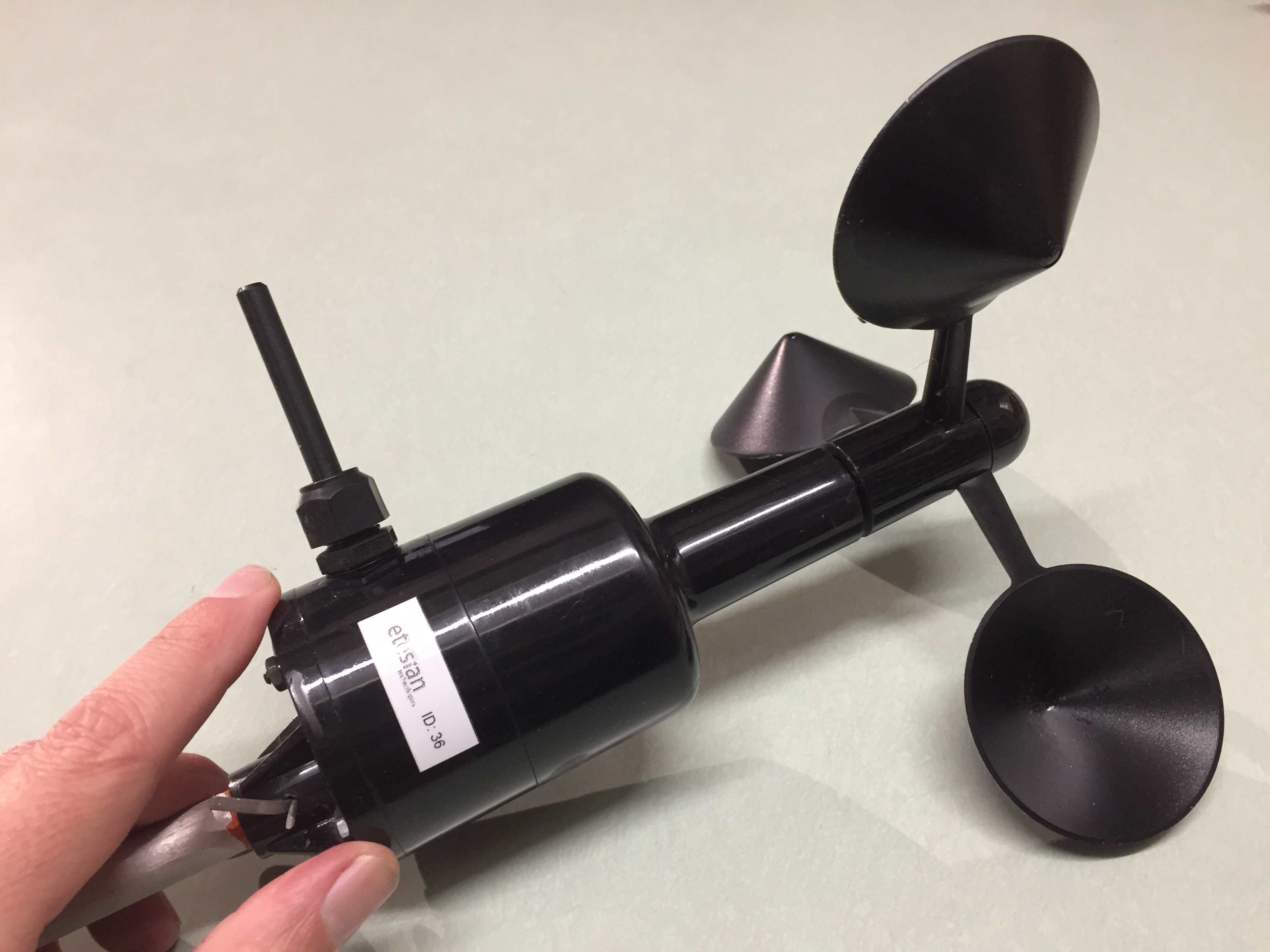
A wireless, batteryless, self-powered anemometer from Etesian Technologies provides near real-time wind speed data for turbine control. The one-piece sensor/transmitter should be attached to the tower 1 to 2 rotor diameters below the tower top. The anemometer is supplied with a 1/2-inch aluminum post.
Tip
Anemometer support systems will necessarily vary with tower type. It is the responsibility of the installer to devise a durable support boom. One simple method uses bent 3/4-inch EMT or IMC electrical conduit extending at least one meter from the tower. Experience has shown that at least three (3) stainless steel hose clamps must be used to secure the anemometer post to the boom and the same again to secure the boom to a pipe tower. Using fewer than three (3) clamps will fail – resulting in down-time and costly anemometer replacement. The anemometer, support boom, and hose clamps should be inspected for loosening or damage at least annually.
Tip
A useful modification to this anemometer would be to weather protect the gap between the rotating cup piece and the supporting axial assembly. When water collects and freezes in this gap, the anemometer stops. If the turbine generates power without an anemometer signal, the firmware generates a fault condition and the turbine furls until the anemometer thaws. Significant downtown can result if freezing conditions persist.
 |
 |
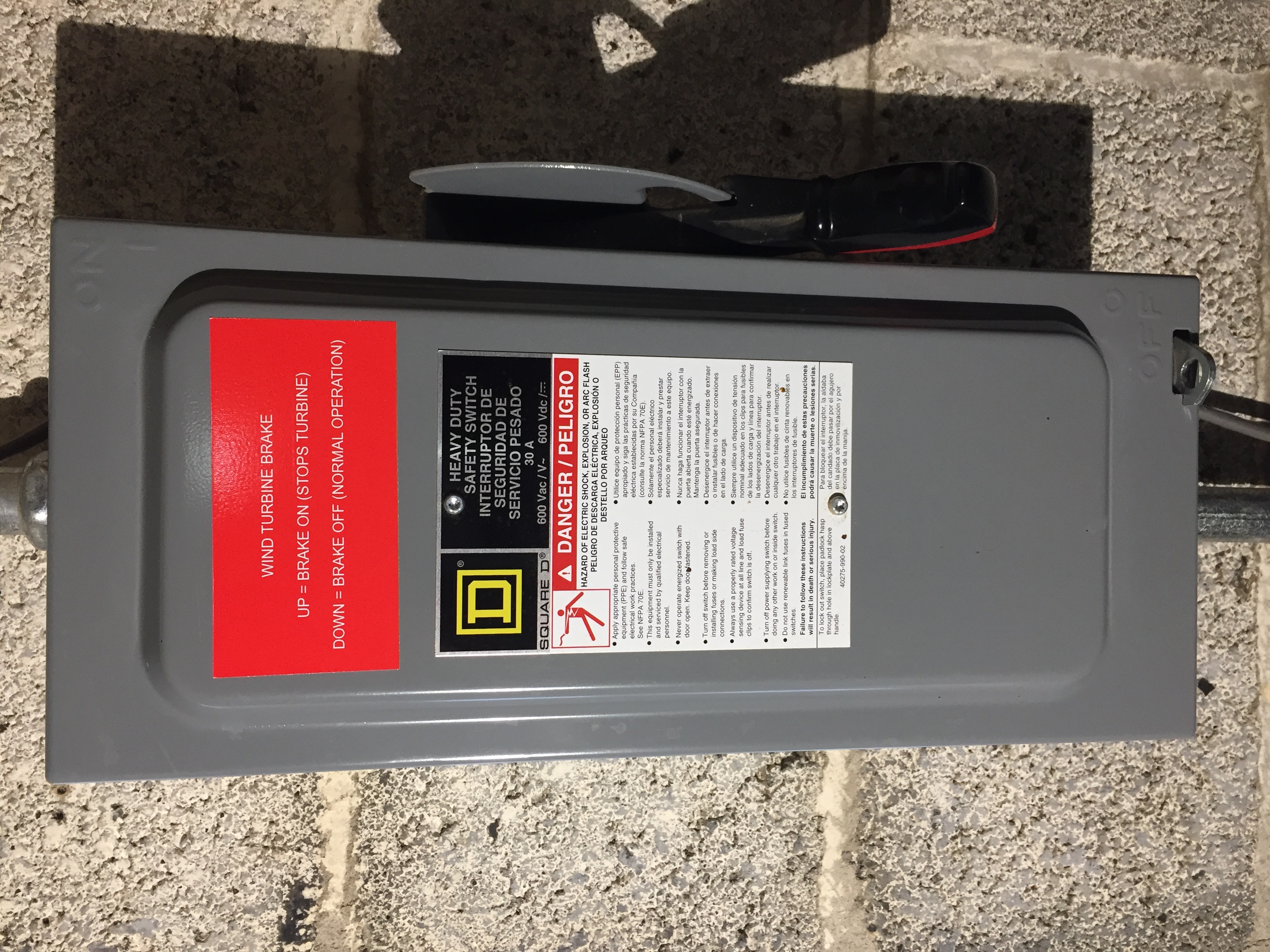
A 600VDC, 30A, 3-pole, non-fusible disconnect is provided as a turbine brake switch. Its function is to short together the three (3) alternator power conductors. The brake switch is typically installed near the tower base, but can be located anywhere along the wiring path from the tower base to the indoor balance-of-system components. Its application as a brake switch differs from that of a conventional “disconnect”: the UP (ON) position shorts (stops) the alternator; the DOWN (OFF) position unshorts it. The brake switch label should make this clear.
 |
Type 1 surge protection devices (SPDs) are used to protect against lightning-induced current surges on all conductors between the W2 turbine and other system components. Applicable standards for outdoor wind and PV installations are specifically noted in this document. Other useful reference materials are found on the same site.
All eleven (11) non-ground conductors in the tower cable are individually protected by a DIN-rail mounted array of SPDs inside a NEMA3R junction box at the tower base. Three (3) turbine power conductors utilize a Phoenix Contact 277/480V AC (nom.) Type 1 SPD; four (4) stepper motor drive conductors and two (2) shorting contactor conductors utilize Phoenix Contact 100V DC (MCOV) Type 1 SPDs; and two (2) reed switch sensor conductors utilize a Phoenix Contact 6V DC (MCOV) Surge Protection Plug.
Tip
As climate change worsens, proper lightning protection becomes ever more important with the increasing prevalence of severe thunderstorms. Experience has proven to us that all towers – even if well-grounded, with or without a wind turbine – will be struck by lightning. Simply put – it's not if, it's when. And when lightning strikes, the investment in high-quality SPDs that actually work will then seem worth it.
 |
 |
Warning
Do not attempt to start the turbine before thoroughly reading and understanding System operation and subsections describing System shutdown, System startup, and Turbine operating modes. Failure to do so could result in safety hazards to persons as well as permanent, catastrophic damage to the system.
The W2 turbine is supplied with the following grouped parts:
Turbine body: pre-assembled with Alternator and Frame components.
Tail assembly: tail arm, tail vane, fasteners.
Yaw assembly: yaw stem, snap ring, vibration isolators, fasteners.
Hub assembly: hub plates, nose cone, fasteners.
Blades: set of three (3), pre-drilled and balanced.
Tower cable and strain relief, Brake switch, and Surge Protection Devices.
Caution
An inventory of shipped parts should be taken upon receipt. Any missing or damaged parts should be reported to WWE as soon as possible. From experience, we strongly recommend that you follow the order of assembly steps described below.
Begin by pulling the electrical cable up through the tower leaving about 4 feet at the top (first photo below). Next, install the tower top adapter (second photo below), threading the cable through it. Finally, thread the cable through the yaw stem and bolt the yaw stem flange to the tower top flange (third photo below). The yaw stem flange should be sandwiched by the rubber isolators as shown in the second photo below. The correct torque will be just enough to begin compressing the hard rubber – the manufacturer recommendation is 126 N·m with Grade 10.9 bolts. Do not over-tighten the bolts!
Caution
The yaw stem and turbine body are heavy and will require more than one person and/or mechanical lifting assistance to safely position these parts with respect to the tower top.
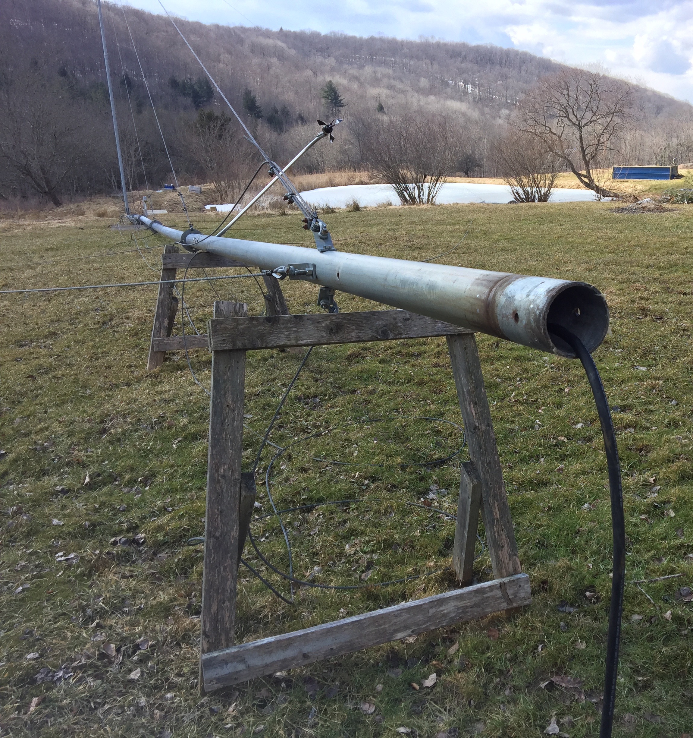 |
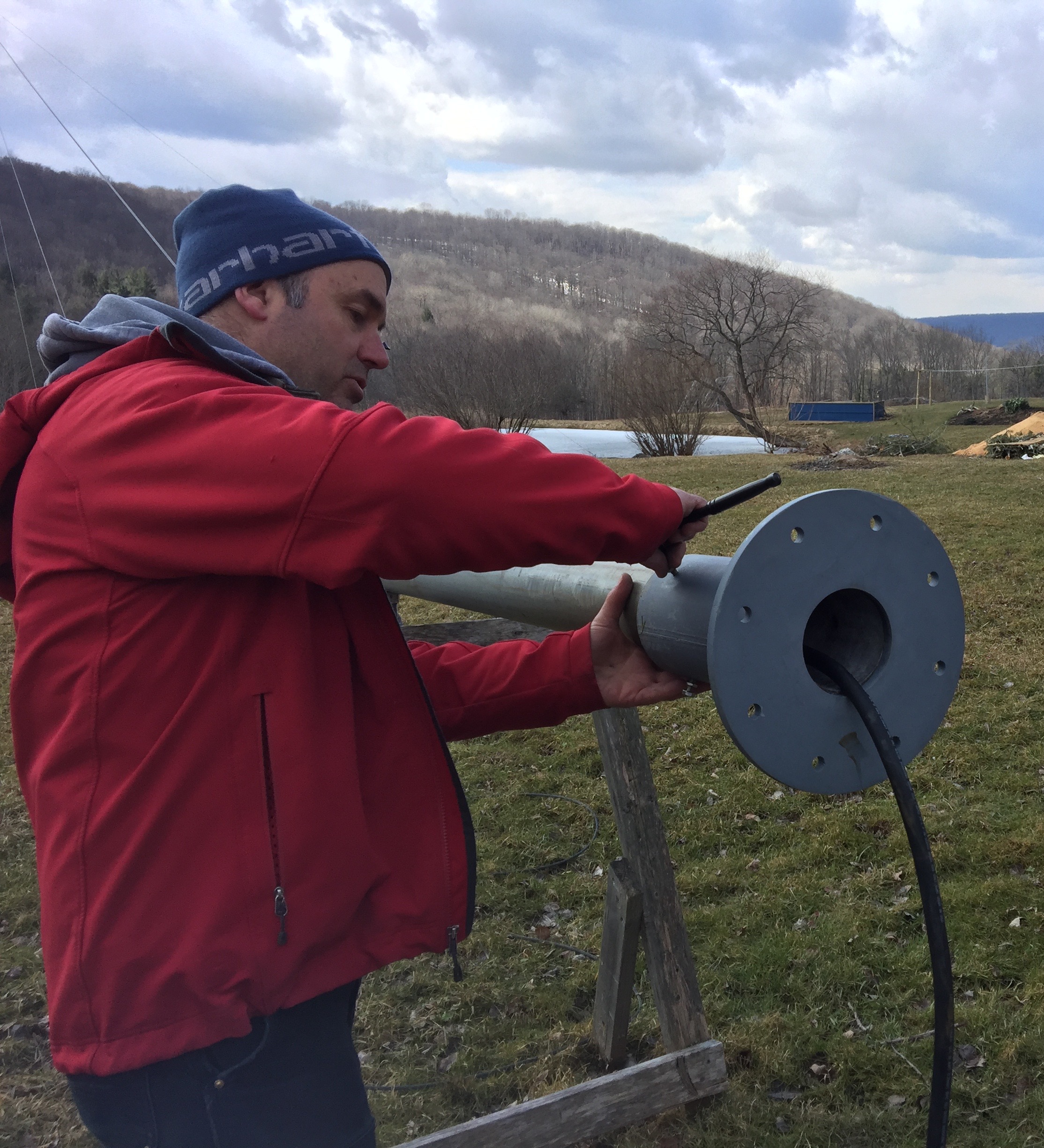 |
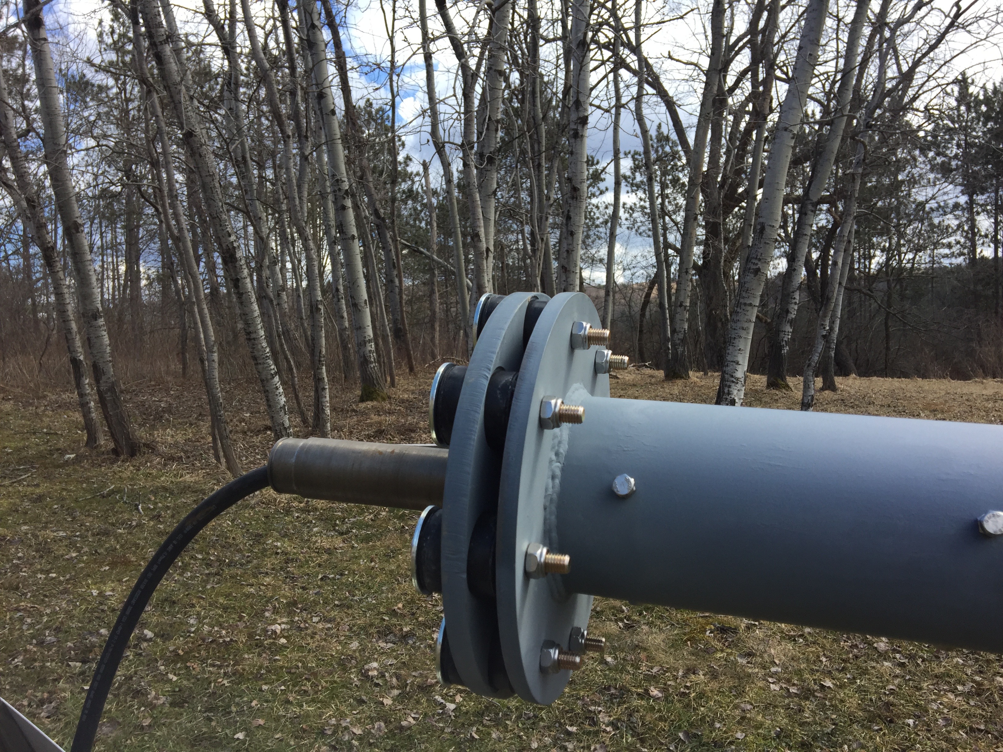 |
Tip
Applying a thin coat of grease or viscous oil to the yaw stem will help the turbine to slide on more easily.
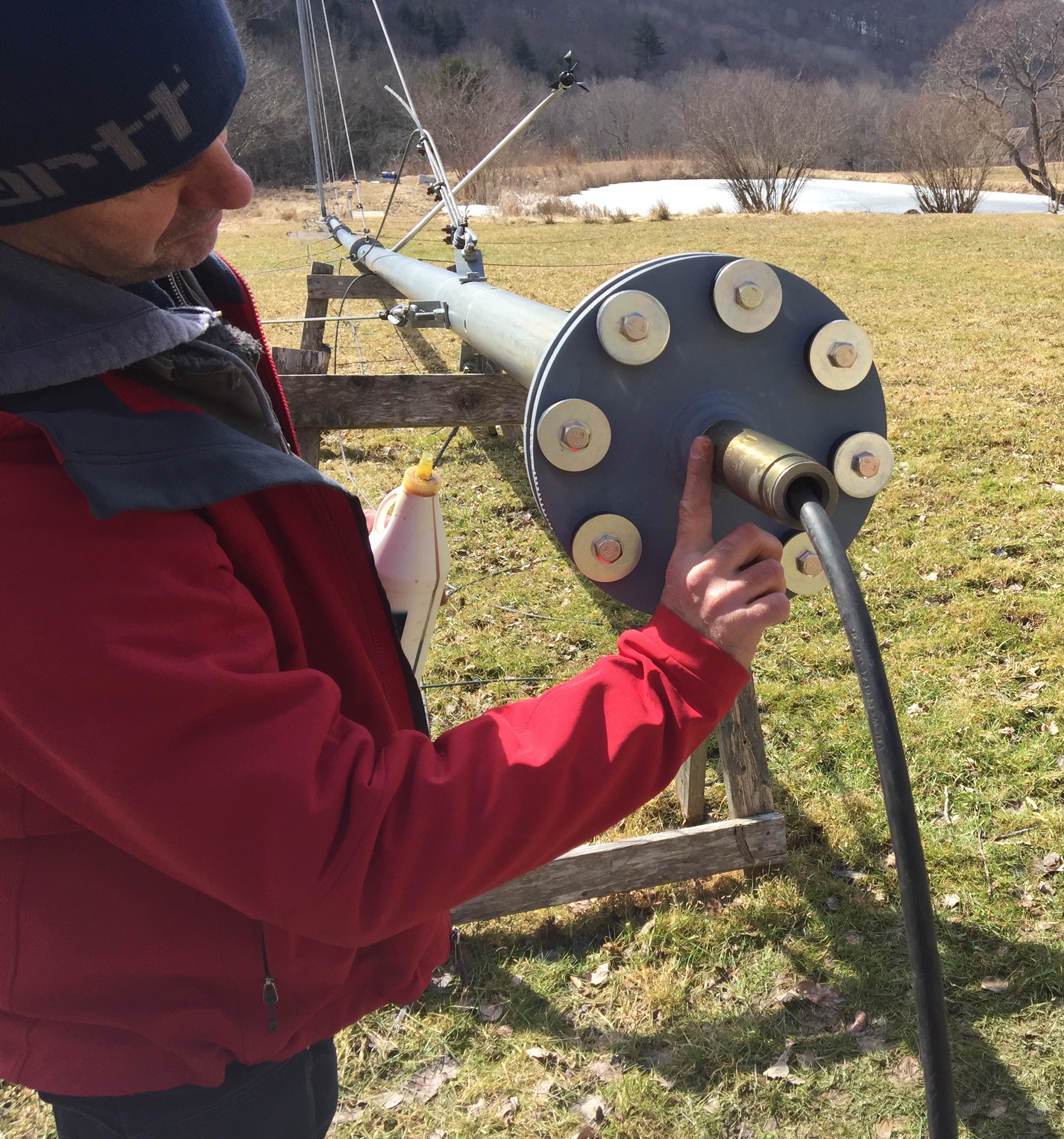 |
First, remove the snap ring from the machined grove at the top of the yaw stem (use snap ring pliers if available), then slide the turbine body gently onto the yaw stem, guiding it through the bottom and top bearings in the turbine frame, until it seats and rotates freely. With the turbine seated, reattach the snap ring onto the top of the yaw stem.
 |
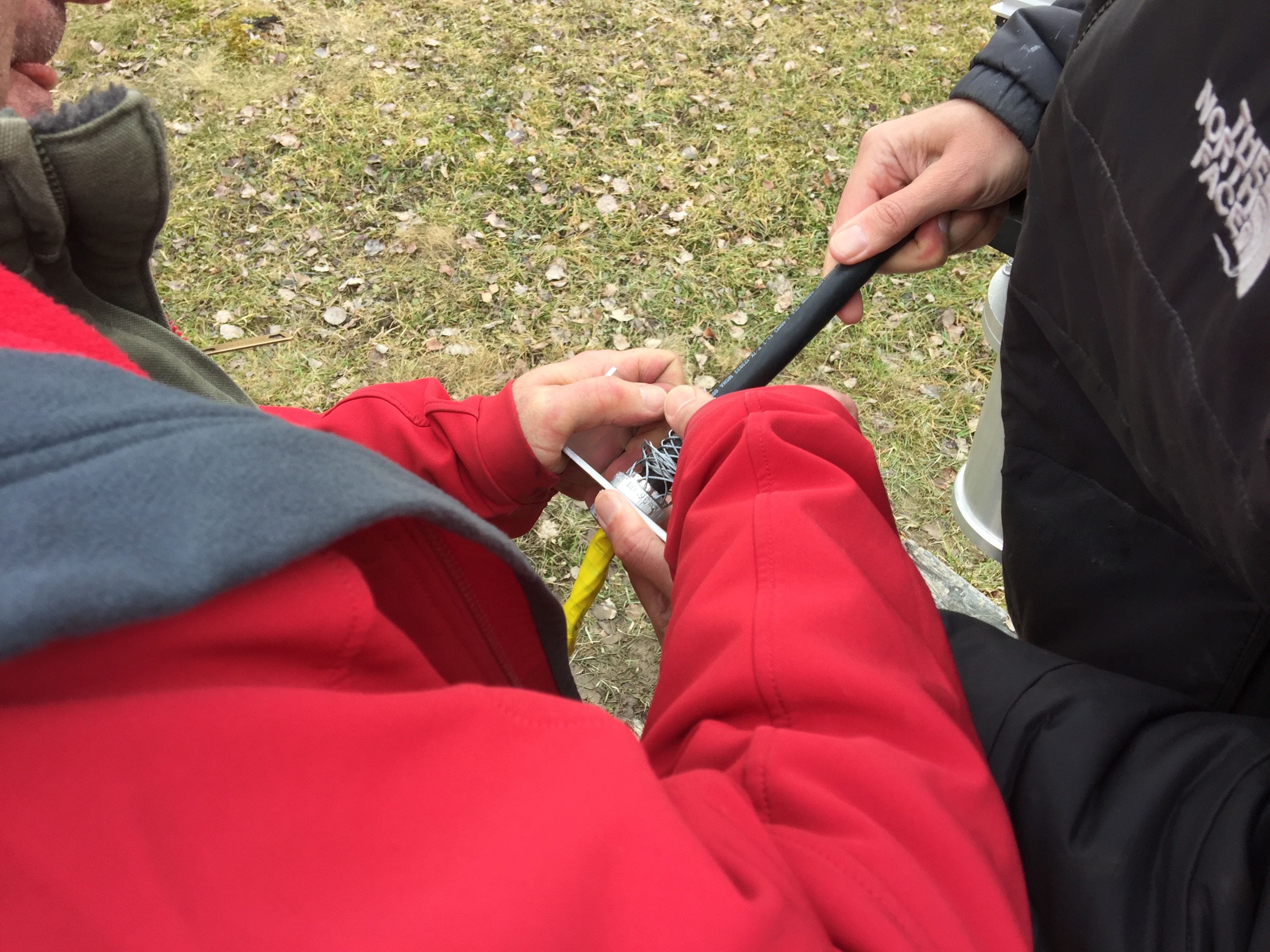
The cable grip “points” down the cable toward the tower base, in the same direction as the U-bracket “feet”. Tape up the twelve (12) ferruled conductors into a tight narrow bundle, then compress and expand the grip wires toward its base while an assistant slides the cable through (see photo). Be careful to not pinch your fingers!
 |
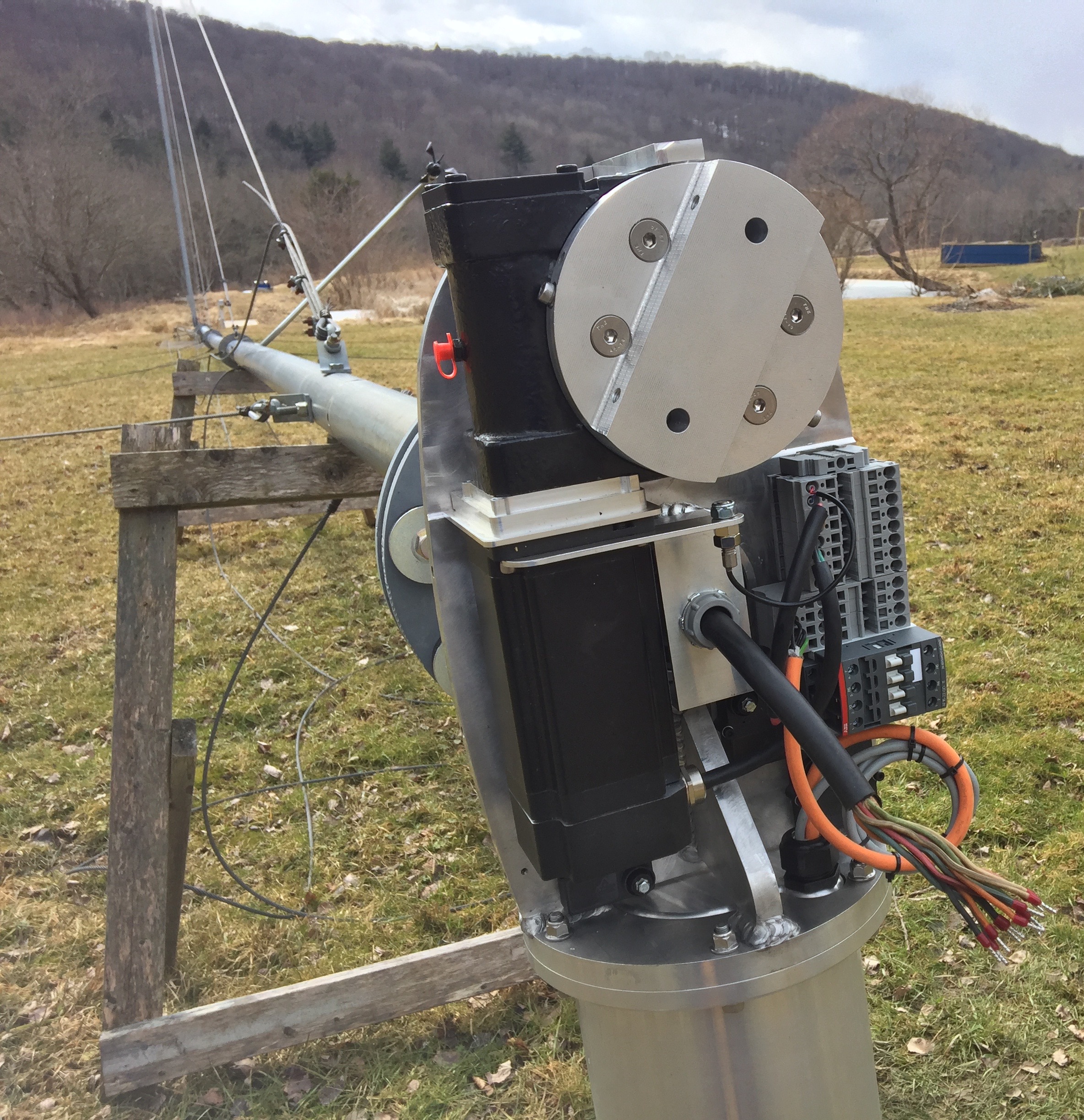
Push just enough cable (about 12 inches) beyond the grip to allow making unstrained connections to the spring terminals on the nacelle platform. From the tower base, pull back on the electrical cable until U-bracket “seats” against the straight facets around the the upper yaw bearing support (see Tower cable and strain relief). The U-bracket will support the cable just above the yaw stem outlet. Insert each of the cable conductors into its respective spring terminal. In shipped units, the spring terminals are labeled and/or color-coded to uniquely match each of the tower cable conductors.
Tip
Using spring terminals: Most important – find a flathead screwdriver with a shaft (not tip) size that the spring terminal insert can accommodate without excessive insertion force. Push the screwdriver all the way into the insert until it stops, at which point the teeth of the terminal should be fully open, with the pushed-in screwdriver now firmly held in place by the terminal housing. If you can't push the screwdriver in all the way without excessive force, try a slightly smaller screwdriver. Insert the wire into the terminal, being careful not to allow insulation past the terminal teeth, and pull out the screwdriver.
 |
Tip
Once the spring terminal connections are made, it is very helpful at this point to initialize the W2 turbine controller in Auto Mode. Assuming no controller startup errors, doing so will position the tail coupling plate at a “fully furled” tail angle between 80 and 90°. If this orientation is not convenient for attaching the tail arm, using the Wired remote put the controller into Manual Mode and rotate the coupling plate to a more suitable angle. In the photo above, the tail coupling plate is at an angle of about 30°.
Caution
If the W2 turbine controller is powered on, be certain to put the turbine in Manual Mode throughout the remainder of the assembly process.
Once the tail assembly is attached, do not attempt to move the tail with the controller unless you provide physical assistance to it as it rotates. The stepper motor cannot overcome the weight of the tail, and trying to do so will cause the motor to “slip” accompanied by a loud grating noise. While this should not harm the motor (according to the manufacturer), WWE recommends against it.
Bolt the tail arm to the Tail coupling plate, then bolt the tail vane to the tail arm with the supplied fasteners [include torque specs]. Once the Tail assembly is in place, the turbine will become weighted toward the tail because the hub and blades are not yet attached.
 |
Tip
WWE recommends assembling the rotor (hub + blades) separately, apart from the turbine, and then sliding the assembled rotor onto the alternator shaft. This minimizes the potential for blade damage and allows easy checking for equal tip-to-tip blade distances (see below for how to do that). However, if this is not possible, the carbon fiber blades are light enough for one or two people to safely support them while assembling the rotor in place on the shaft. It may be helpful to raise the tower enough to give sufficient tower clearance above the ground to allow free rotation of the blades – again, this minimizes the potential for blade tip damage.
Caution
While the carbon fiber blades are very strong, they can be damaged by drops or sudden impacts. Take extreme care to protect the blades, especially the blade tips, during rotor assembly. Also take care to match blade labels with corresponding hub plate labeling. Failure to do so could result in an unbalanced rotor leading to turbine damage.
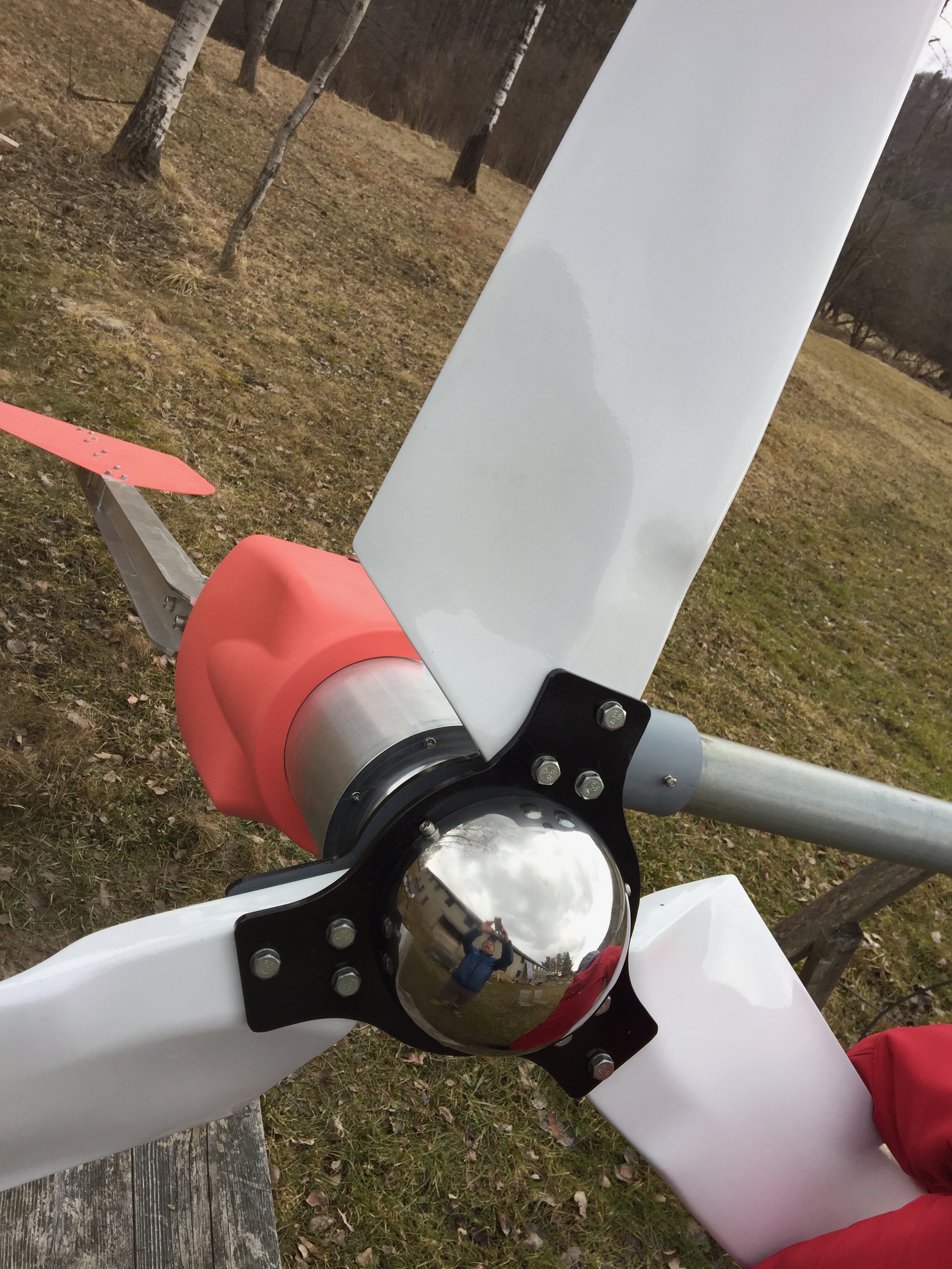
Each turbine blade is pre-drilled and labeled. Blade labels must be matched to corresponding labels on the hub plate assembly [see diagram and photos] for proper rotor balance and blade tip separation. Loosely fit the blades into the hub assembly leaving enough “give” in the blade bolts to allow small movements of the blade tips. Measure the three (3) tip-to-tip distances and calculate the average. The goal is to make each tip-to-tip distance equal to the average within a tolerance of 3-mm (about 1/8-inch). Keep in mind that moving one blade tip will change two blade-to-blade distance measurements. After moving a blade, repeat the measurements and recalculate the average. Repeat this process until the measurments are in agreement within tolerance. When tightening the blade bolts, be careful not to move the blade or over-torque these bolts [include torque specs].
 |
With the rotor assembled, screw on the large Nyloc™ nut on the alternator shaft with a ???-inch socket (1 or 2 shaft threads should be visible beyond the end of the nut) [torque specs]. Finally, attach the stainless steel nose cone to the hub with the supplied hardware. It may be necessary to rotate the nose cone to find the best alignment of its three (3) pre-drilled holes with the hub tabs.
 |
Install the tower cable, Brake switch, and Surge Protection Devices. These will typically be located at the tower base near a junction box where buried conduit emerges with wiring from balance-of-system equipment (typically a few hundred feet away). In some installations, it may be more convenient to locate the brake switch closer to the balance-of-system components. Junction box type and component configurations at the tower base will vary from site to site. One example, following the electrical schematic [see diagram], is shown below.
 |
Attach the Wireless anemometer 1 to 2 rotor diameters (10 to 20-feet) below the top of the tower. A bent 6- to 8-foot piece of 3/4-inch EMT or IMC secured by at least three (3) stainless steel hose clamps (or other fastening technique) works well as an anemometer boom (see photo). The boom should point towards the prevailing wind direction for the site.
 |
The sections below cover installation of a Legacy tower, an ARE Telecom tower, and discusses the possibilities of Other towers. This is followed by the hugely important topic of Tower grounding. A discussion of tower Site selection completes the section.
A tilt-over, 127-foot guyed tower used as a development platform for the W2 turbine is a legacy product designed by Robert Preus and Abundant Renewable Energy. ARE is no longer in business and this tower is not commercially available. However, the design is robust and well-documented in the ARE tower manual and could be readily replicated with permission and/or a licensing agreement.
 |
Not to be confused with the ARE legacy tower, an unrelated company, ARE Telecom designed and supplied a tilt-over, hydraulically-lifted monopole to WWE for another W2 System. This system is still in the process of installation.
 |
Tip
Extensive experience with conventional towers of various types now leads us to strongly recommend that alternative tower designs for small wind turbines must be developed. For example, towers constructed of lightweight, recyclable materials such as laminated (engineered) wood products are in development in Sweden and Germany for large turbines. Obviously, the concept is applicable to smaller towers.
Caution
All towers will be struck by lightning.
And some will be struck more frequently than others depending on geographic location. As such, “lightning protection” is more appropriately called “lightning mitigation”. Lightning mitigation is accomplished by implementing various levels of tower grounding ranging from simple grounding conductors and electrodes to extensive ring or grid grounding schemes to elaborate tower appurtenances.
Determining what level of lightning mitigation is appropriate for a given site really comes down to researching what has worked at other tower sites in the area. Without adequate grounding – sooner or later – lightning will cause extensive damage to system components.
It is the responsibility of the tower owner to implement adequate lightning mitigation methods. While the W2 System design and installation recommendations attempt to minimize lightning susceptibility, WWE cannot accept responsibility or be held liable for lightning damage to any component of the W2 System.
A complete discussion of lightning mitigation methods is beyond the scope of this manual, but there are many useful resources and voices of experience that can help:
Siting a small wind turbine always involves compromises. There is no such thing as an “ideal” site for a tower – for a wind turbine or otherwise. Wind resource (elevation, topography), property boundaries, buildings (residential or not), other infrastructure (roads, power lines, airports, and other rights-of-way), natural treasures (trees, hills, birds, bats, etc.), and most of all, objections (from neighbors and permitting authorities) must be considered in tower site selection. A complete discussion of all of these factors is beyond the scope of this manual, but there are many useful resources and voices of experience that can help:
The primary function of the W2 controller is to control the power output of the W2 turbine in real-time by adjusting the tail angle according to prevailing wind conditions and rotor speed. The controller is designed around the Arduino Due microcontroller with an Ethernet “shield”.
The turbine controller also receives, processes, and transmits Modbus data from attached Morningstar controllers and a Nuvation Low-Voltage BMS. The controller saves all turbine and Modbus data to a micro-SD flash memory card on the Ethernet shield. For System software and control, the controller creates and directs several data streams (UDP) to one or more servers; a Data server saves the data and provides a web-based System monitor web page for real-time and historical data analysis; an Update server handles controller configuration requests and firmware updates. Streaming (UDP) data from an Outback Radian-series Inverter bypass the controller and are sent directly to the system server.
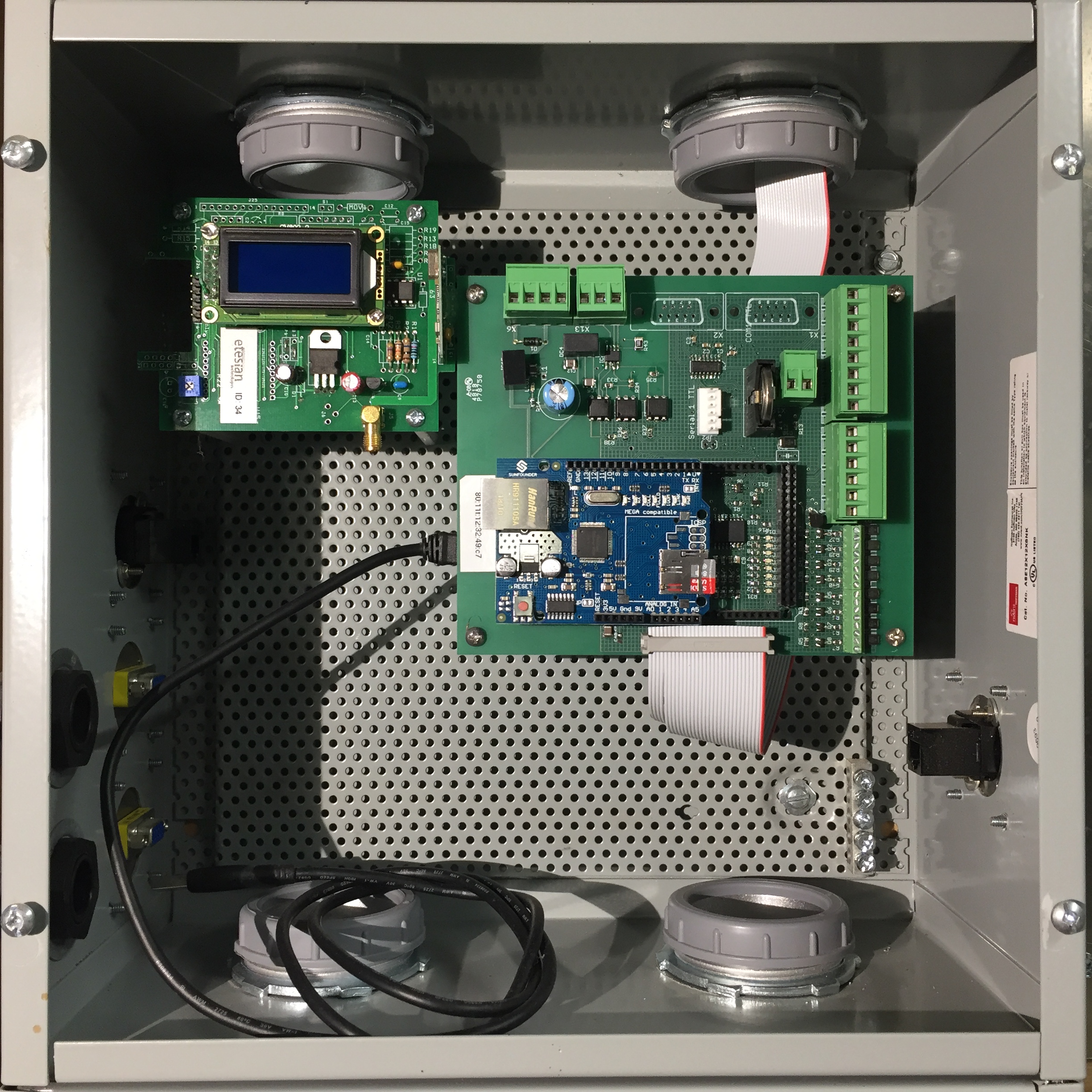
The Revision 3 (R3) turbine controller is divided into three (3) separate compartments each of which houses distinct components. Components with heatsinks are located in the upper Power compartment for optimal heat dissipation. Logic and networking components are located in the middle Logic compartment. Terminal blocks, DC fuses, shorting contactor relay, and a large film capacitor are located in the lower Wiring compartment.
The controller must be installed indoors in a non-freezing, non-condensing environment. This diagram shows the layout and wiring of controller components as well as wired connections to external devices.
Caution
Use a multimeter when servicing the controller. Voltages may be present inside the controller even after the battery has been disconnected due to slow discharge of capacitance in various components of the system.
 |
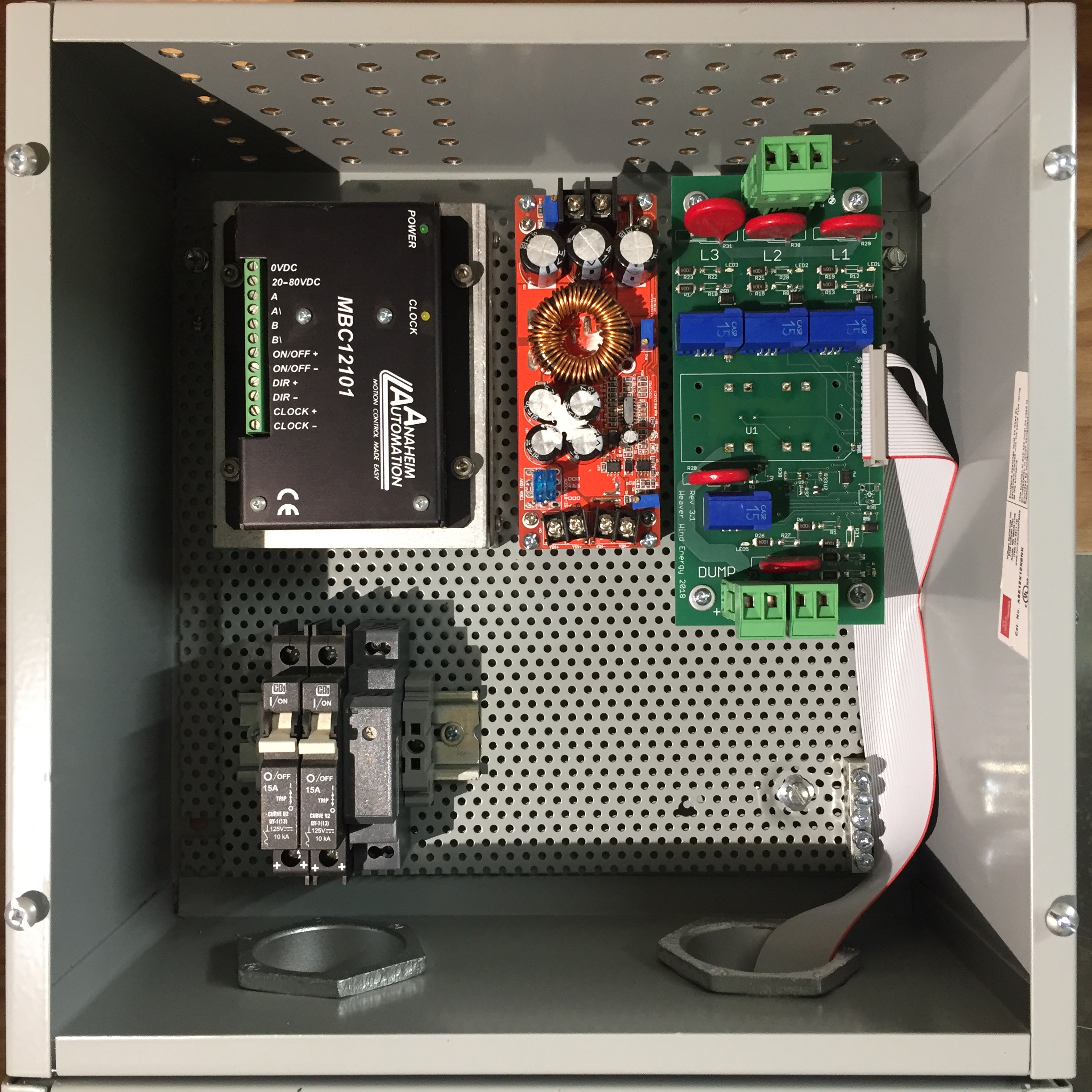 |
The power-handling circuit board receives variable-voltage, variable-frequency, 3-phase AC (labeled L1,L2,L3) from the turbine via a 3-terminal connector (seen at top in the photo) and rectifies it to DC. The rectifier (labeled U1) is mounted with a heatsink on the opposite side of the board (and so is not visible in the photo). Near the top of the board, LED1, LED2 and LED3 respond to turbine AC on L1, L2 and L3, respectively. Depending on controller settings and system status, variable-voltage DC is directed to either the TS-MPPT-600V controller or to the High voltage diversion load (HVDL) via adjacent 2-terminal connectors (seen at bottom in the photo). The HVDL connector is labeled DUMP. The Power Board is connected via a ribbon cable to the Controller logic board in the middle Logic compartment.
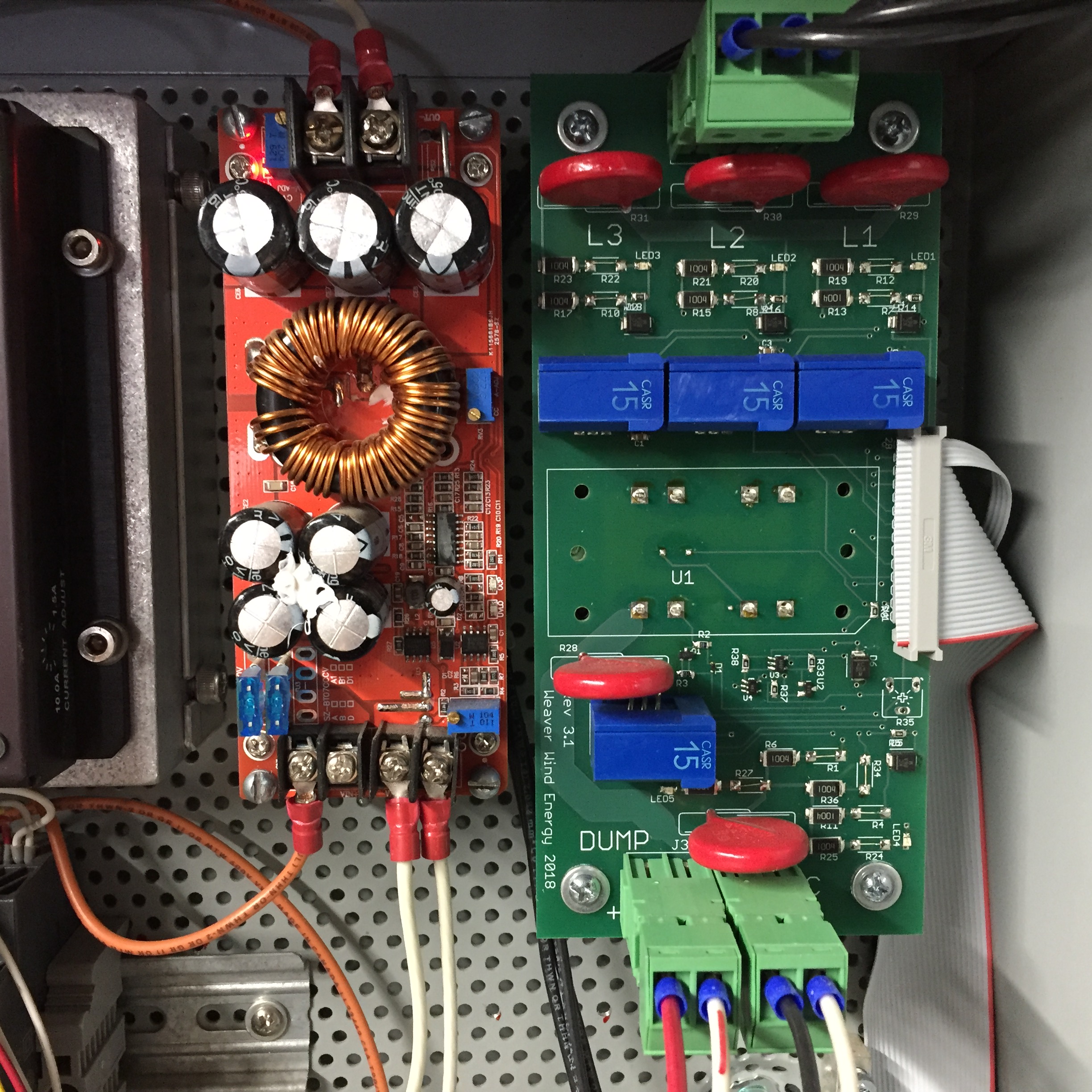 |
A bare board 48-to-80V DC-DC converter supplies power to the adjacent Stepper motor drive.
Caution
The converter's three (3) potentiometers have been adjusted by WWE to deliver approximately 80 VDC constant-voltage with output current varying according to the load imparted by the stepper drive and motor; misadjustment of the potentiometers may result in failure or sub-optimal performance of the tail drive train.
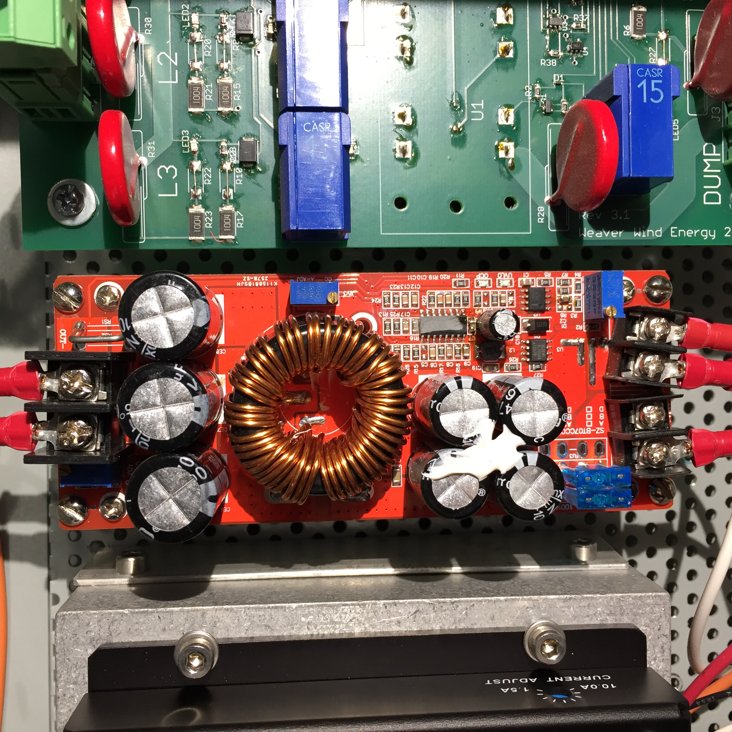 |
.jpg) |
A DIN-rail mounted 48-to-12V DC-DC converter supplies power to the Controller logic board as well as the Anemometer base unit. It is located in the upper compartment of the controller adjacent to a pair of 15A DC circuit breakers. The breaker labeled “80V” is the Power On/Off switch for the Stepper motor drive. The breaker labeled “12V” is the Power On/Off switch for the Controller logic board and Anemometer base unit.
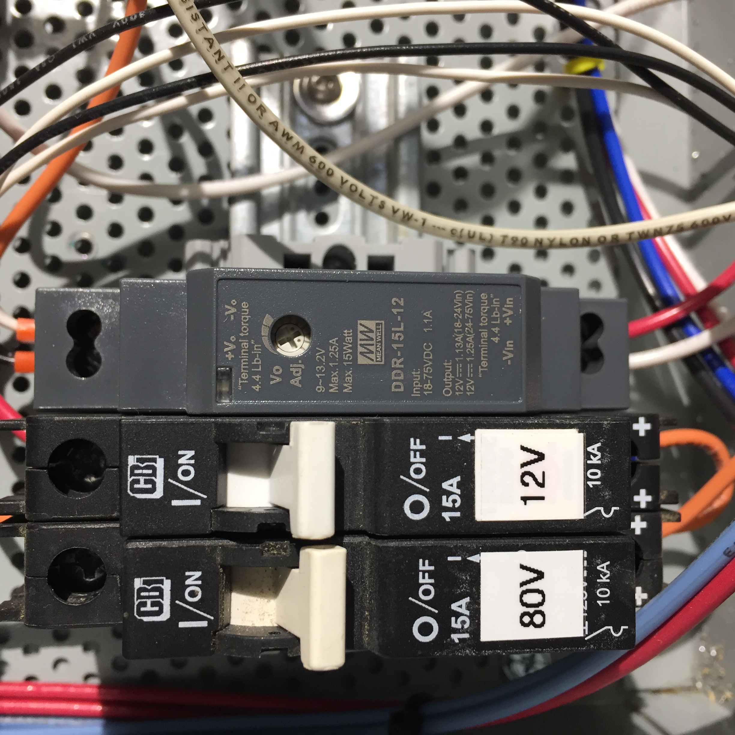 |
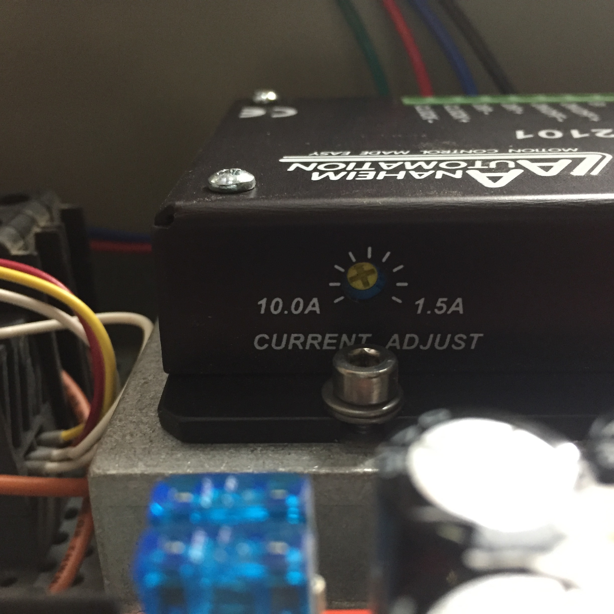
An Anaheim Automation MBC12101 stepper drive located in the upper controller compartment is used to control the Stepper motor and slewing drive in the turbine. The “Current Adjust” potentiometer on the side of the device should be set at the “11-o'clock” position; higher currents may cause damage to the drive and/or motor.
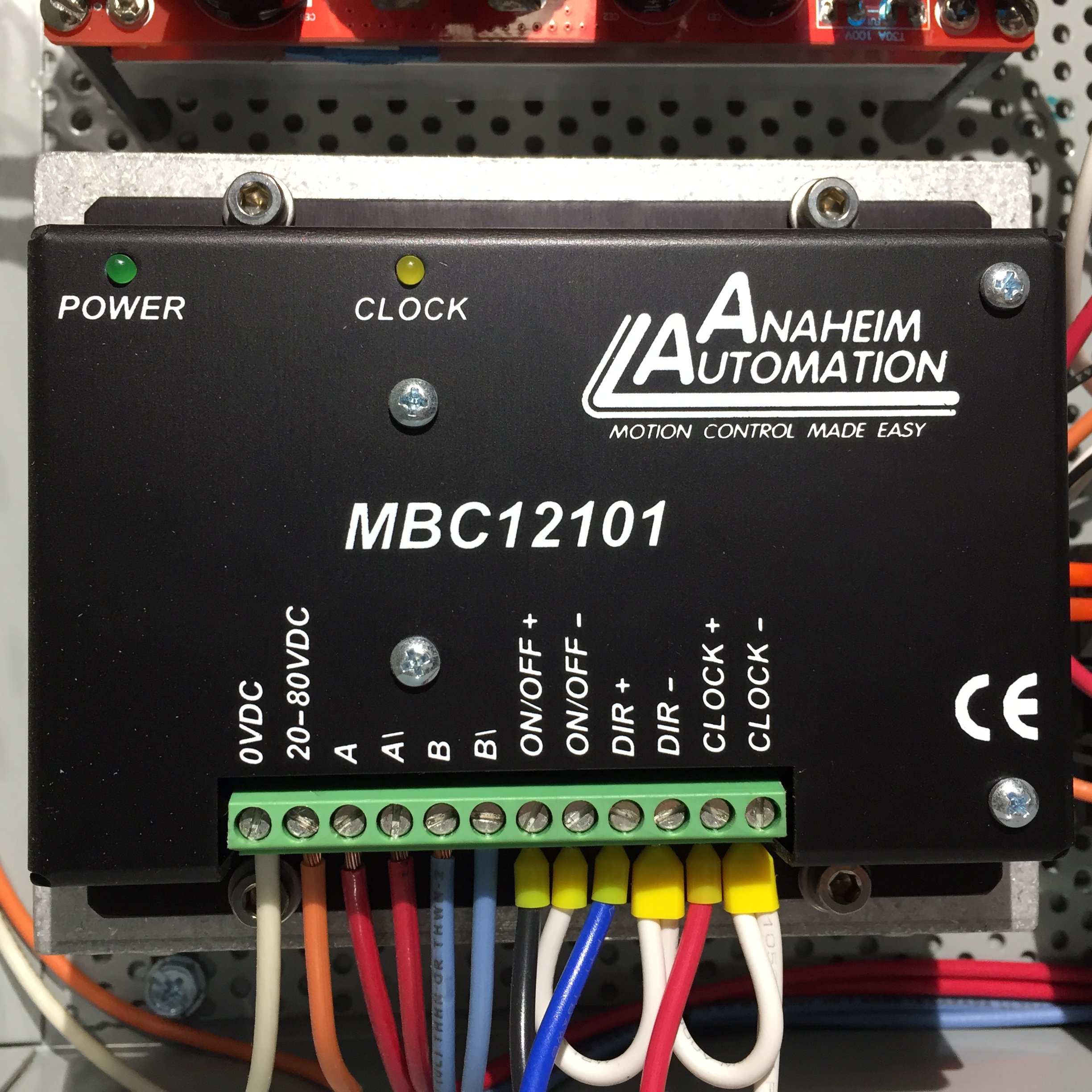 |
 |
 |
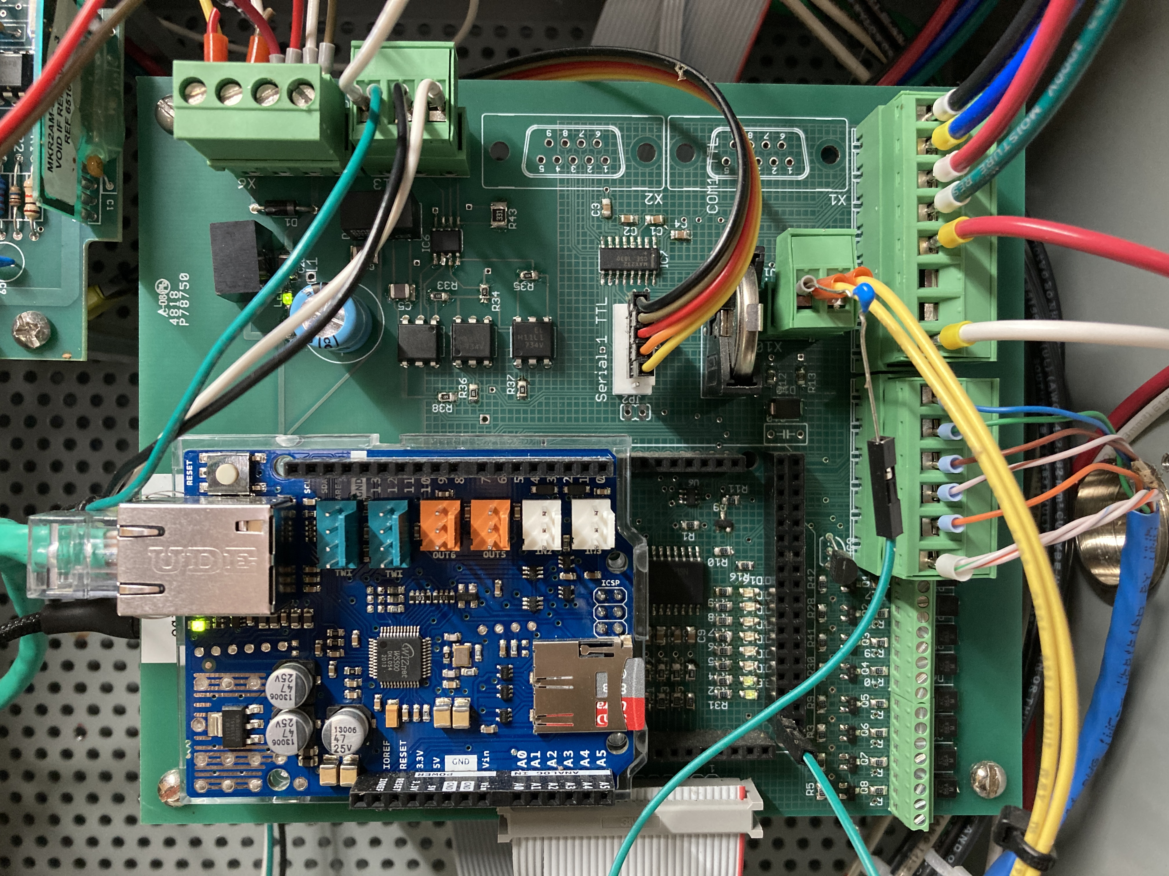
The controller Logic Board hosts an Arduino Due microcontroller with an Ethernet Shield Rev2 (blue circuit board). In the photo below, the Arduino Due is on the opposite side of the circuit board (and so is not visible). On the visible side, clockwise from upper left are connectors for: 12VDC In/Out power (4-terminal), Modbus/RTU (EIA-485) for Morningstar controllers (3-terminal), serial TTL from the Anemometer base unit (5-pin), Reed switch input (2-terminal), Stepper motor drive and shorting contactor control (8-terminal), Wired remote control (6-terminal), ribbon cable (to power board), and the Arduino shield Ethernet cable. The micro-SD flash memory card is easily accessible on the Ethernet shield board.
Note
Stepper motor drive and shorting contactor control terminal assignments (from top to bottom in the photo below):
Stepper motor drive ON/OFF(+)
Stepper motor drive DIR(+)
Stepper motor drive CLOCK(+)
Stepper motor drive GND
Shorting Contactor control out
UNUSED (formerly, non-stepper motor UNFURL control)
UNUSED (formerly, non-stepper motor FURL control)
Shorting Contactor control return (GND)
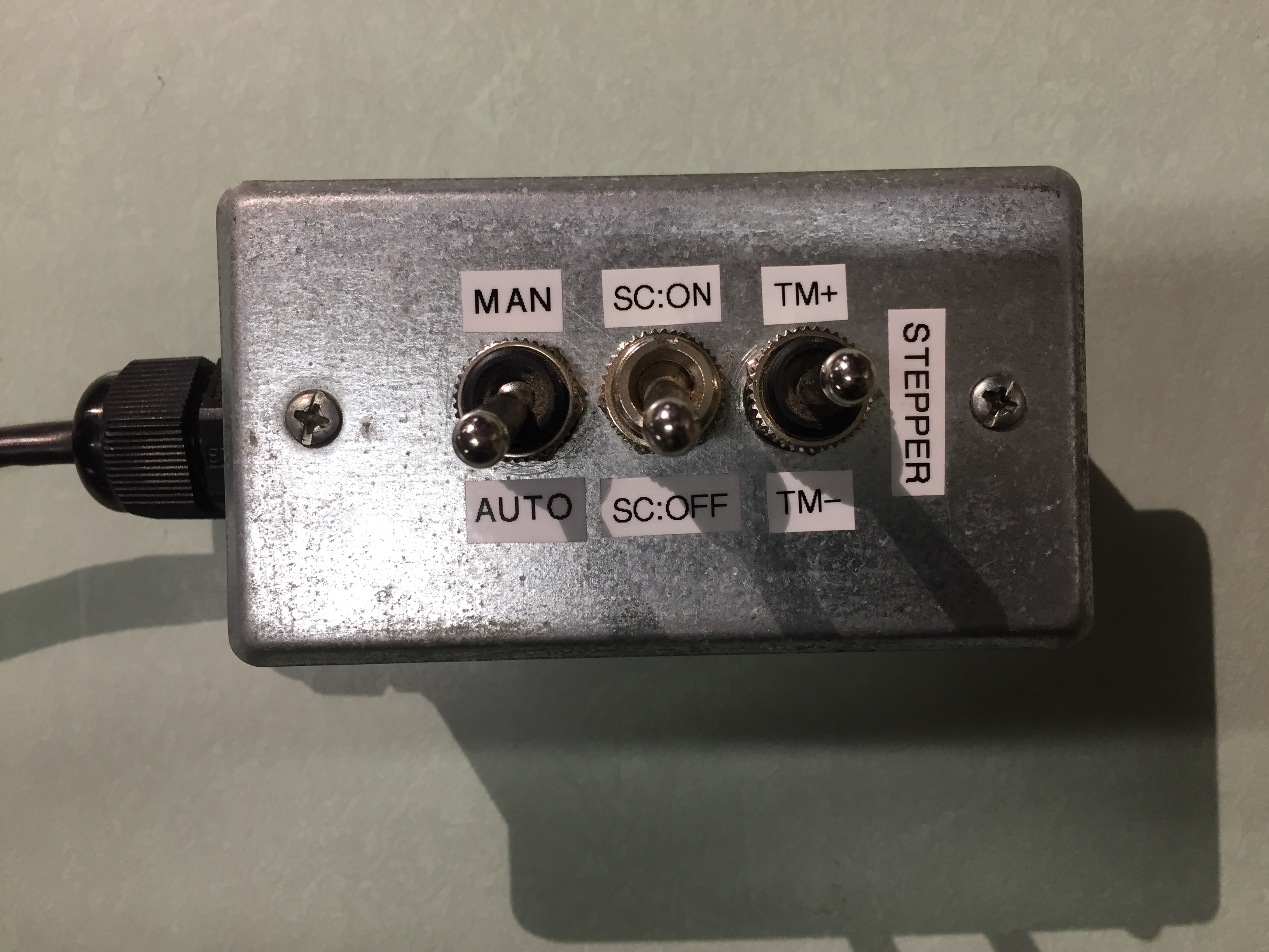
Wired remote terminal assignments (from top to bottom in the photo below):
Drive stepper motor (TM+)
Drive stepper motor (TM–)
Close shorting contactor (SC:ON)
Open shorting contactor (SC:OFF)
Set Manual Mode (MAN | AUTO)
GND
 |
Note
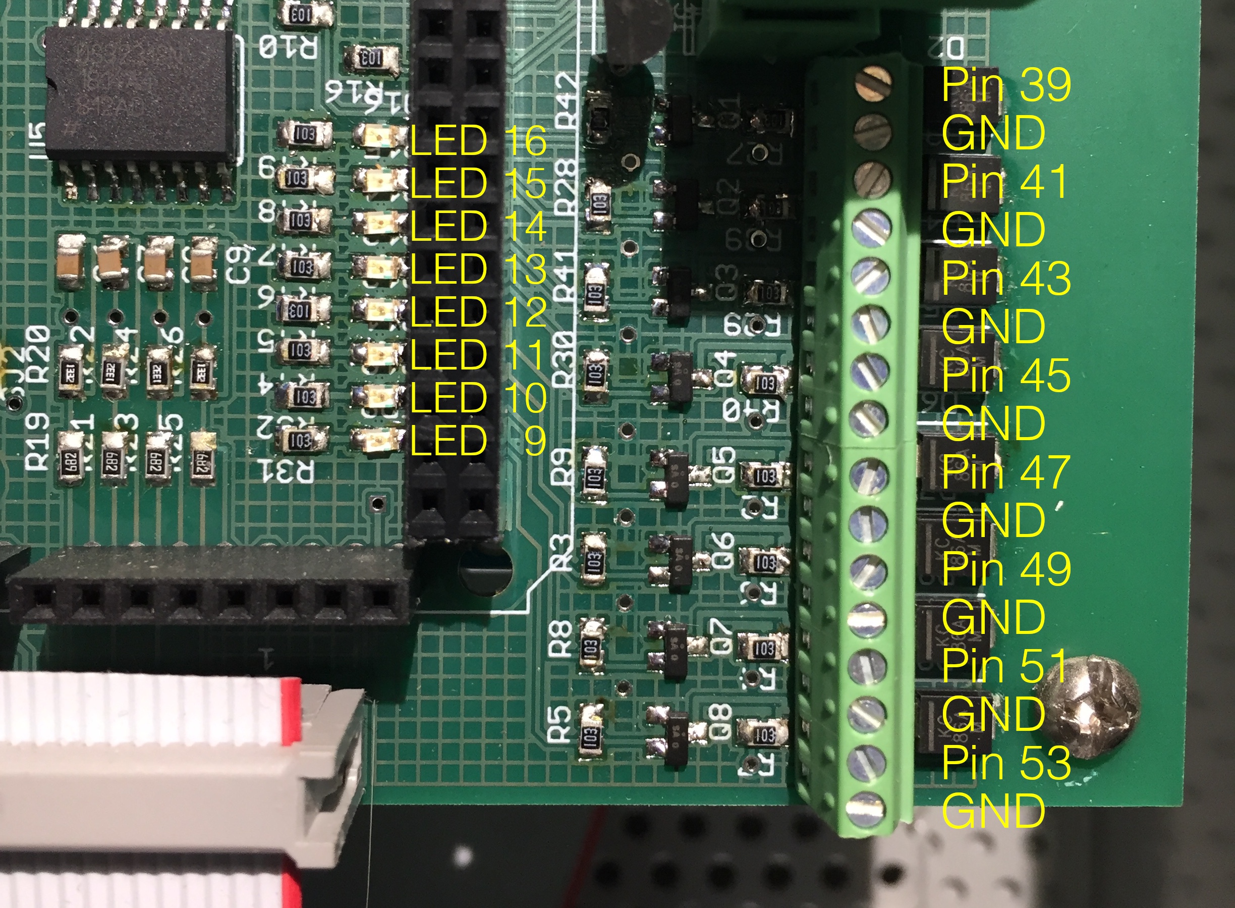
LED assignments (from top to bottom in the photos above and below). An LED lights when its associated condition is true. Pin assignments (and LED meaning) may change with firmware updates.
LED1 (upper left corner of board): +12 VDC Power In
LED16 = Arduino Pin 38: Reed Switch (RS) Active
LED15 = Arduino Pin 40: Unassigned (OFF)
LED14 = Arduino Pin 42: HVDL Active
LED13 = Arduino Pin 44: Shorting Contactor (SC) Shorted
LED12 = Arduino Pin 46: Tail Motor (TM) Active (+)
LED11 = Arduino Pin 48: Tail Motor (TM) Active (–)
LED10 = Arduino Pin 50: Interrupt Timer (1 sec ON, 1 sec OFF)
LED9 = Arduino Pin 52: Main loop() Counter (5000 iterations ON, 5000 iterations OFF)
16-pin screw terminal connections to Arduino pins (from top to bottom in the photos above and below). These are 0-5 VDC, bidirectional and isolated from the Arduino to prevent damage. Ground (GND) pins separate Arduino pins. These connections are currently assigned (in firmware) to external logic analyzer inputs to assess hardware and firmware function; other uses are possible.
Arduino Pin 39: STATUS1_PIN_1
Arduino Pin 41: STATUS1_PIN_2
Arduino Pin 43: STATUS1_PIN_4
Arduino Pin 45: STATUS1_PIN_8
Arduino Pin 47: STATUS2_PIN_1
Arduino Pin 49: STATUS2_PIN_2
Arduino Pin 51: STATUS2_PIN_4
Arduino Pin 53: STATUS2_PIN_8
 |
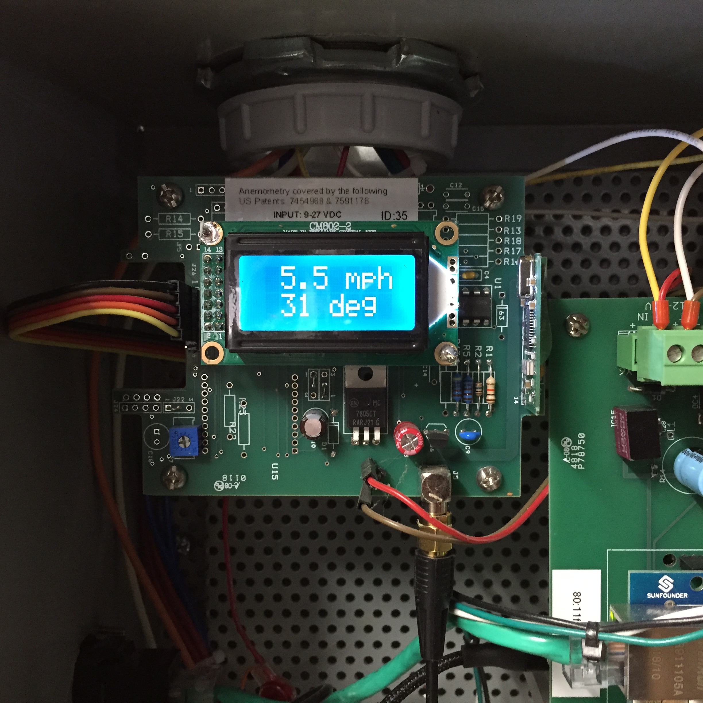
A custom Etesian Technologies “base unit” is integrated into the logic compartment as a bare circuit board. The base unit provides digital wind speed and temperature data to the controller via a 5-pin serial TTL interface. This device is a receiver which is connected via coaxial cable to an outdoor Yagi antenna. The antenna receives a line-of-sight signal from a tower-mounted Wireless anemometer sensor/transmitter.
 |
There are three (3) communications ports on the left side panel of the controller logic compartment: Ethernet (RJ-45), Modbus (RJ-45), and Modbus (DB-9).
 |
The Ethernet port handles: (1) outgoing UDP data streams – to server ports 58328-58332; (2) a minimal HTTP server on controller port 80 for getting and setting Controller operating parameters; and (3) Modbus/TCP for communication with the Nuvation Low-Voltage BMS.
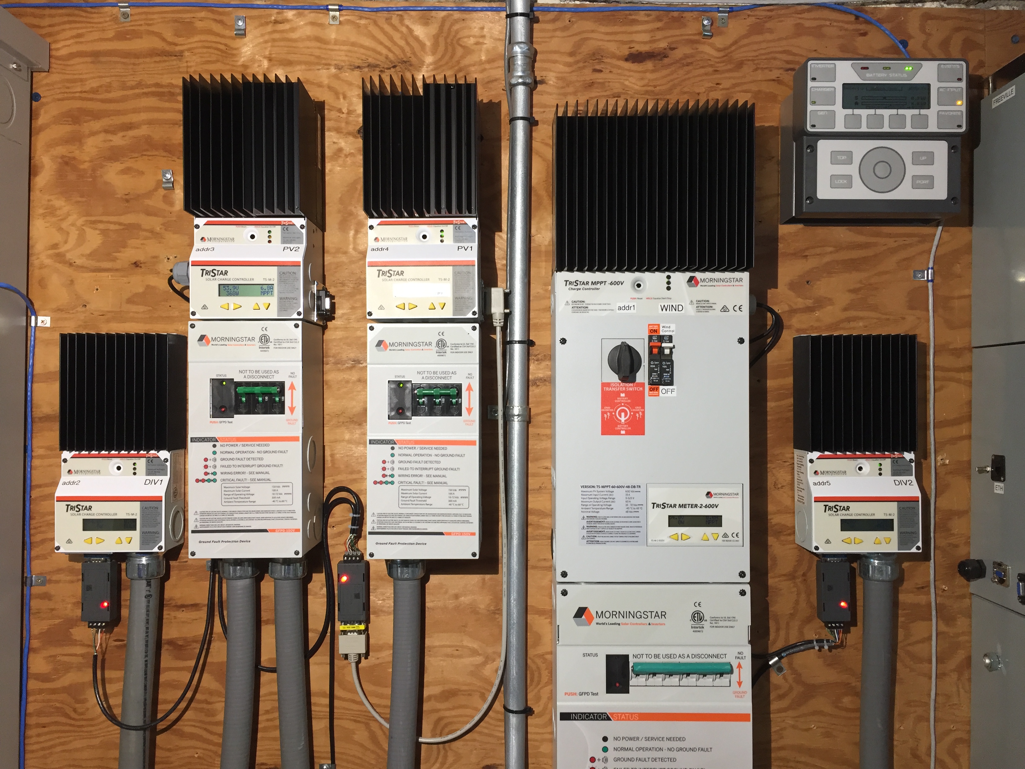
The Modbus (RJ-45) port provides a connection point to the controller (typically at the end) in a Modbus/RTU (EIA-485) chain of Morningstar devices; as a minimum, this is one TS-MPPT-600V and one TS-60 controller. In the photo below, five (5) Morningstar controllers are networked. TS-60 and TS-MPPT-30 (PV) controllers require RS232-to-RS485 adapters.
 |
The Modbus (DB-9) port serves as a convenient access point for configuring the Morningstar controllers with a laptop and an RS485-to-USB adapter cable.
 |
Note
A micro-USB cable can be used to connect to the programming or data ports of the Arduino Due microprocessor on the Controller logic board for diagnostic or development work (see Controller firmware).
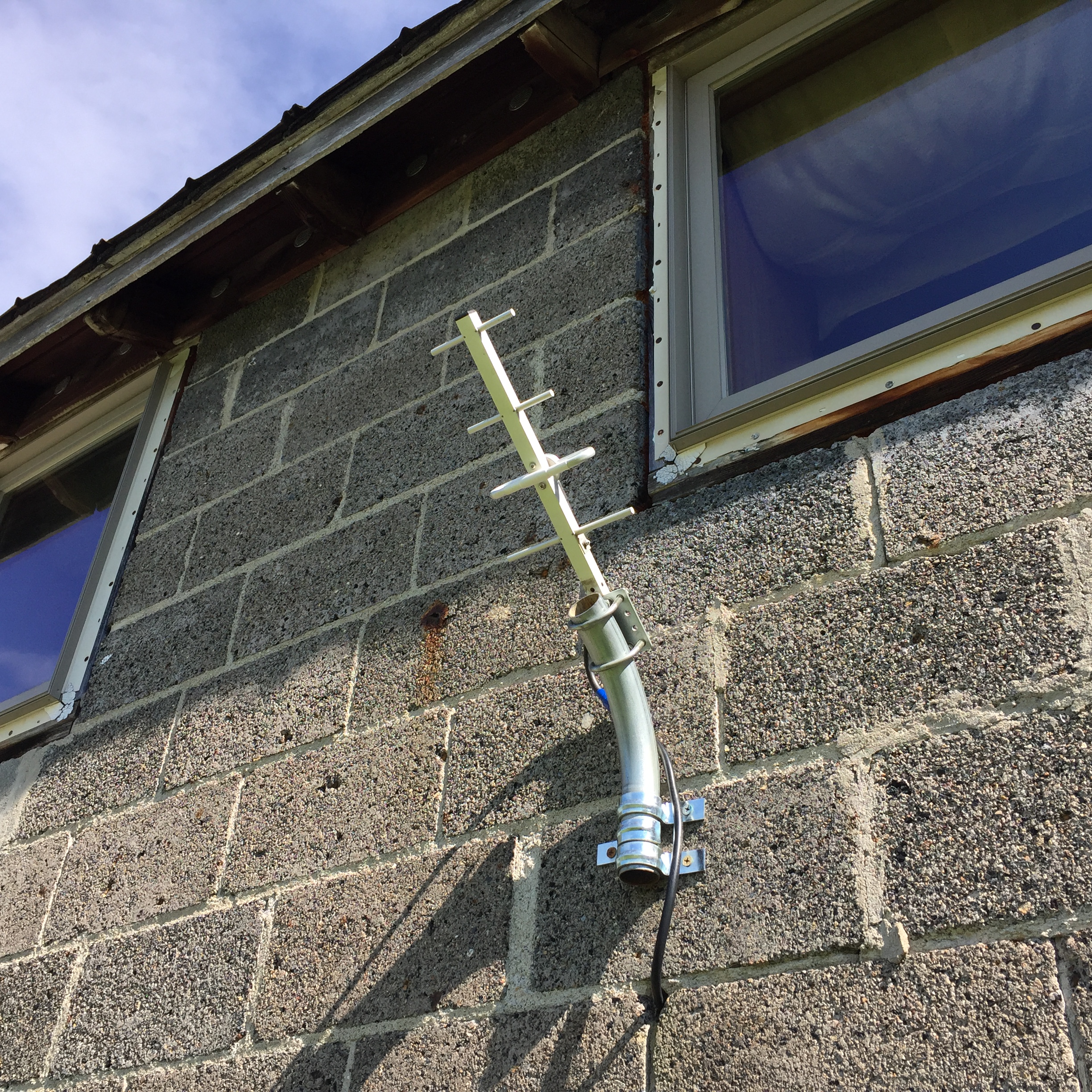
The Yagi antenna supplied with the system must be mounted outdoors in an unobstructed line-of-sight to the tower-mounted Wireless anemometer. Reliable line-of-sight transmission distances of several hundred feet are possible. The Yagi antenna has a N-female connector. A 20-foot N-male to SMA-male coax cable is provided to connect the antenna to the SMA-female connector on the controller logic compartment side panel (see photo in Communications cabling). We recommend using a low-loss N-male to N-female extension cable if a greater distance must be spanned.
Tip
The transmitting antenna on the tower-mounted anemometer is oriented horizontally. For best reception, the Yagi receving antenna should also have its elements oriented horizontally (as shown in the photo below). Outdoor coaxial cable connections should be protected with several layers of high-quality electrical or rubber tape to prevent water penetration into the connectors.
 |
The wired remote control plugs into an Ethernet (RJ-45) connector on the right side Logic compartment of the W2 controller. Cat 5/5E Ethernet cable lengths up to 100 feet have been tested. The remote is used to switch between Auto Mode and Manual Mode. In Manual Mode, the remote gives the user direct control of the turbine tail motor (TM) and shorting contactor (SC). This functionality is extremely useful during assembly, commissioning and maintenance of the turbine in order to move the tail to convenient positions for tower raising and lowering. The remote is also used to perform Tail position recalibration in the event of tail motor slippage or system error.
 |
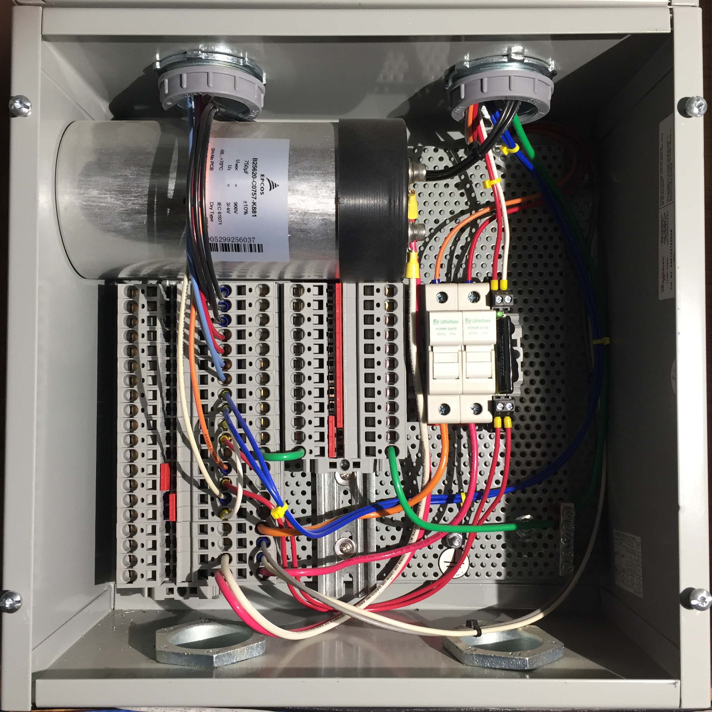 |
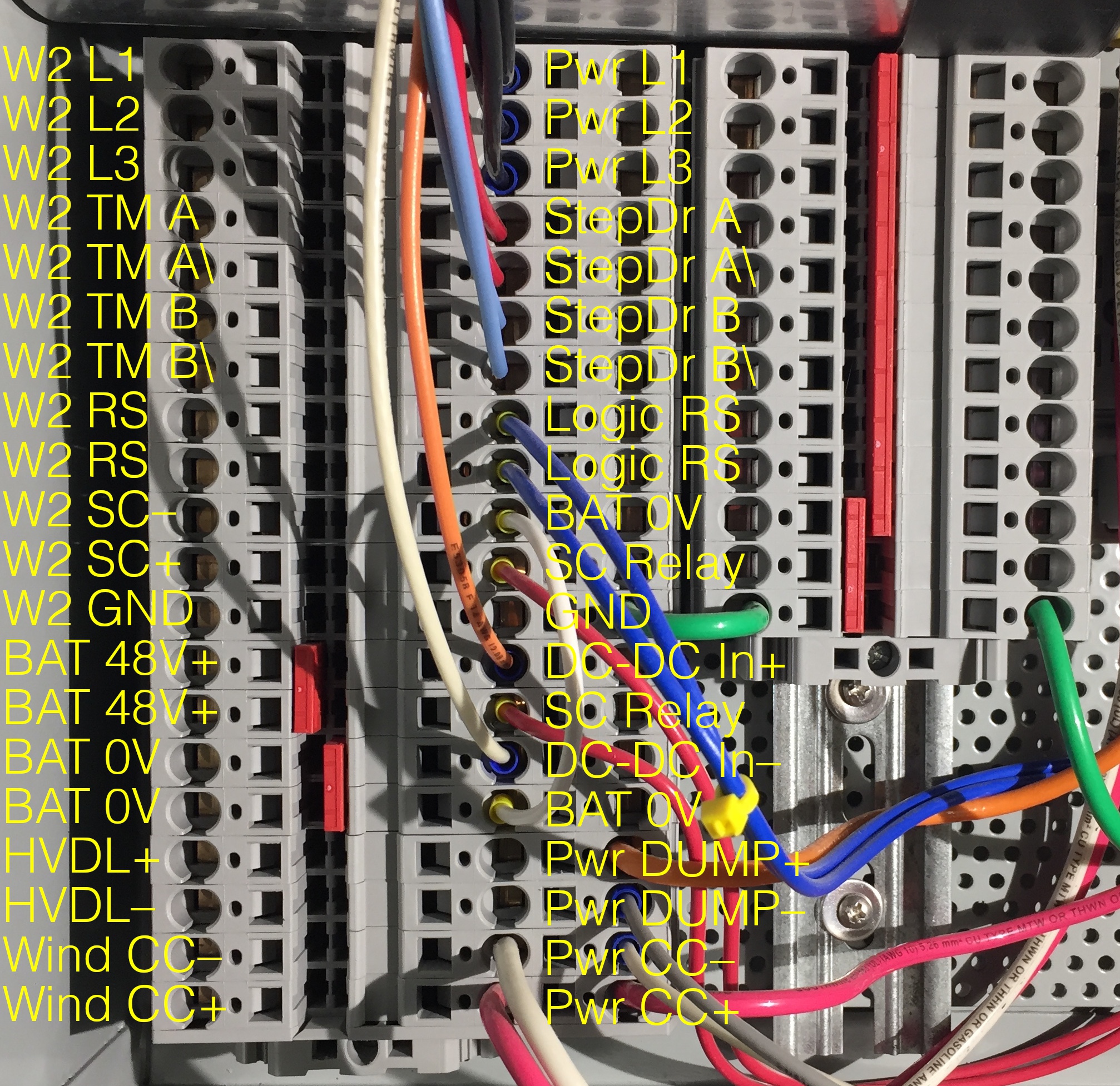
W2 terminals (12): Conductors originating from the junction box at the base of the W2 turbine connect to the left-most column of spring terminals in the wiring compartment. If optional PV is installed, two additional (+) and (–) PV array conductors from the tower base junction box should be routed to the Inverter load center; they do not terminate in the controller.
Caution
Each of the twelve (12) turbine conductors (typically in buried conduit from the tower site) should be color-coded (ideally, matching those of the tower cable) and clearly labeled to avoid any confusion when making connections to the controller. Equipment damage is likely if connections are not made correctly. The controller spring terminals can accommodate wire sizes up to #10 AWG. If larger gauge wires have been used to minimize voltage-drop, a separate junction box must be installed to downsize the conductors before entering the controller.
DC input terminals (4): Battery power is required to run the W2 controller. 48 VDC is routed from (+) and (–) DC busbars in the Morningstar TS-MPPT-600V charge controller into 2 pairs of electrically-bridged spring terminals marked BAT 48V+ and BAT 0V. A 15A breaker (labeled “W2 System Controller”) on the front panel of the TS-MPPT-600V is the power on/off switch for the W2 controller. The reason for doing this (rather than bringing battery power directly from the Inverter load center) is to engage the turbine shorting contactor should the battery connection to the TS-MPPT-600V charge controller be interrupted for any reason. This is a system safety feature.
DC output terminals (4): Two pairs of conductors originating from spring terminals marked HVDL+/HVDL– and Wind CC+/Wind CC– route DC power to the High voltage diversion load (HVDL) or the TS-MPPT-600V, respectively. The system operating state and the HVDL Active parameter (see Controller operating parameters) determine which current path is active.
At the left edge of the photo below, W2, DC input, and DC output wiring has been removed for clarity. Also, MOV's which normally connect the top-most twelve (12) 3-position spring terminals to corresponding 2-position spring terminals (grounding block) are not installed in the photo.
 |
Tip
Using spring terminals: Most important – find a flathead screwdriver with a shaft (not tip) size that the spring terminal insert can accommodate without excessive insertion force. Push the screwdriver all the way into the insert until it stops, at which point the teeth of the terminal should be fully open, with the pushed-in screwdriver now firmly held in place by the terminal housing. If you can't push the screwdriver in all the way without excessive force, try a slightly smaller screwdriver. Insert the wire into the terminal, being careful not to allow insulation past the terminal teeth, and pull out the screwdriver.
Shorting contactor relay control wires are connected to terminals marked “3” and “4” of a DIN-rail mounted relay in the lower controller compartment. The LED on the relay lights when the relay closes, which provides 48V power to the uptower contactor, which holds it open, thereby allowing the alternator to spin up.
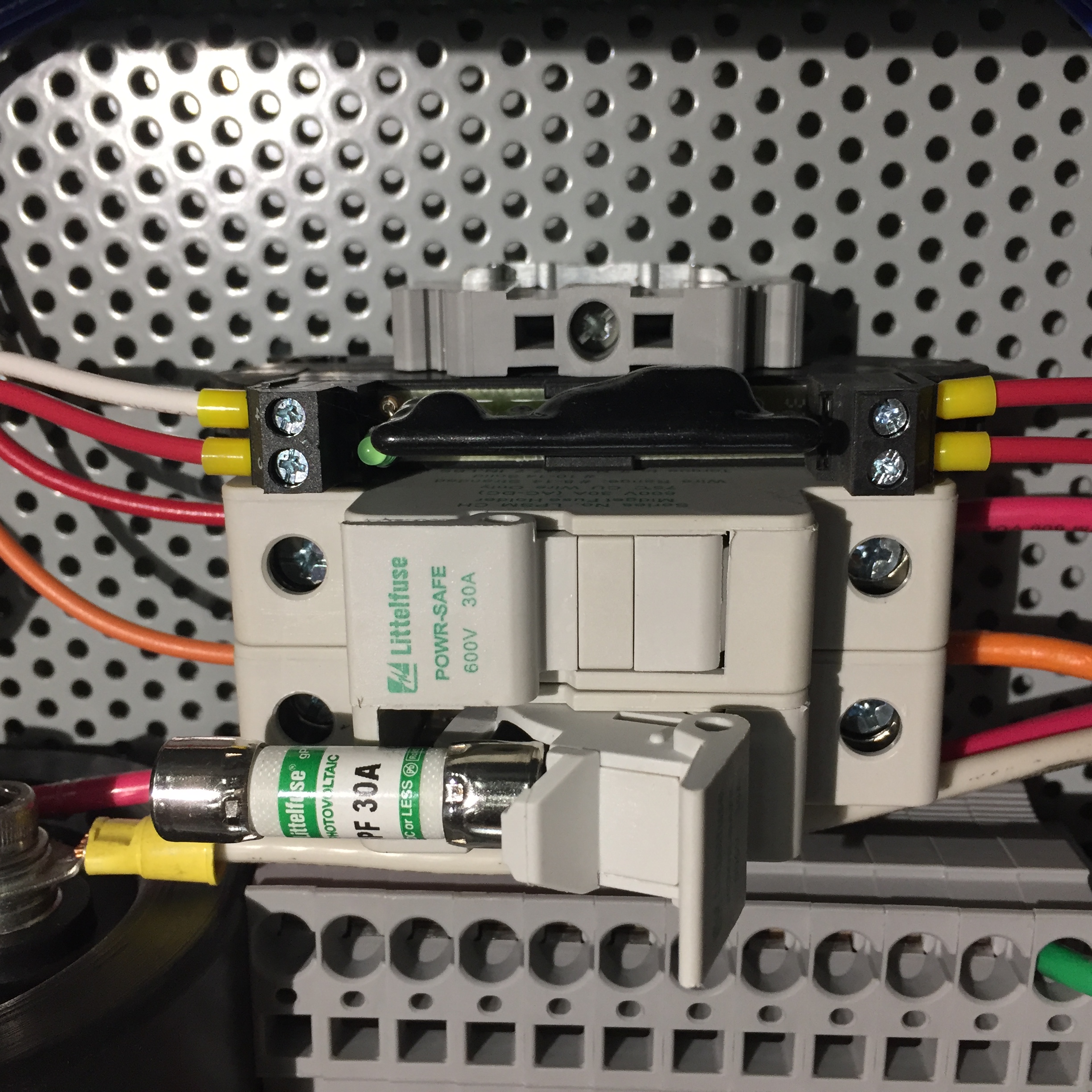
High-voltage DC output from the Power board directed to either the TS-MPPT-600V charge controller or the High voltage diversion load (HVDL) passes through two (2) DIN-rail mounted, finger-safe 30A DC fuses.
 |
A 900V, 750µF film capacitor (shown in the wiring compartment overview photo) buffers DC voltage from the Power board directed to either the TS-MPPT-600V controller or the High voltage diversion load (HVDL).
Note
During field testing, it was found that the HVDL will not function correctly without this capacitor in place to buffer DC voltage from the Power board. More precisely, without the capacitor, the HVDL control algorithm cannot respond fast enough to changes in turbine DC voltage to create a smooth P-V load curve.
Note
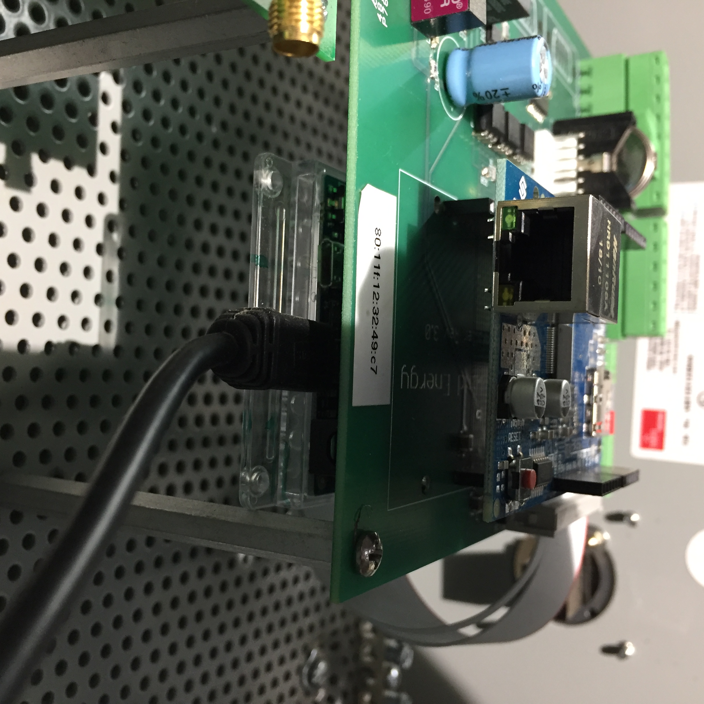
For system development work, the Arduino IDE can be used to make Firmware updates via direct connection of a laptop to the Arduino Due programming port with a micro-USB cable. In the photo below, a cable is attached to the programming port on the back side of the controller logic board. The data port (unused) is visible above the programming port.
Caution
User modification of firmware may cause unexpected system behavior and could lead to permanent, catastrophic damage to the W2 turbine and other system components. For this reason, Firmware updates are typically done only via remote connection to a WWE Update Server which will have the latest fully-tested firmware version. WWE cannot accept any responsibility for damage caused by user-modified firmware.
 |
Controller operating parameters are firmware variables that can be viewed or set (with the button) via a simple web form at the Controller IP address, e.g., 192.168.1.6:49153/parms.html. Changes to parameters are sent back immediately to the controller – and take effect immediately! However...
If Override Updates? = 0, the Update Server will restore user-changed parameters to values stored on the server within Update Interval minutes. See the cautions below and parameter descriptions for more detail.
Caution
Under most circumstances, Override Updates? should be set = 0, and controller operating parameters should not be changed due to potentially adverse effects on turbine operation. The only exceptions are Shutdown State, HVDL Active, PV1 Disconnect, PV2 Disconnect, and WX Override? which are not affected by the Override Updates? parameter setting.
Caution
To make persistent changes to parameters, follow these steps: 1) Set Override Updates? = 1 and enter desired parameter values into the web form, 2) the web form, 3) Wait at least Update Interval minutes for the changes to overwrite values stored on the Update Server, 4) Set Override Updates? = 0, and 5) the web form again. Any parameter may be changed in this manner. Currently, there is no mechanism (not even a firmware update) to restore “default” parameter values except to change them back manually using this same procedure. Once changed on the server, parameter values persist indefinitely!
Tip
Because server updates to parameters may occur after the Controller Operating Parameters web page has been opened in a browser, always reload the page to display up-to-date values before making changes. The page does not auto-update.
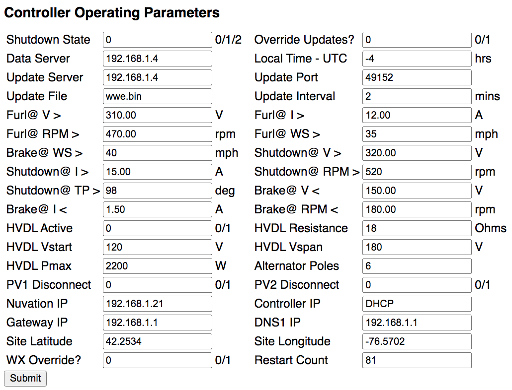 |
Shutdown State— Shutdown state of the wind turbine. 0 = Normal operation. 1 = Normal shutdown. 2 = Emergency shutdown. Default = 1.Tip
Shutdown Stateis the most frequently changed parameter. Except during the firmware update process, only the local turbine operator can change this parameter.Important
After a firmware update or controller reset,
Shutdown Statewill be set = 1. This is the only exception to local control of this parameter. As such, it is necessary to changeShutdown Statefrom 1 to 0 to restart the turbine after a firmware update has occurred.Override Updates?— If this parameter is set = 0, the turbine uses configuration (parameters and firmware) stored on theUpdate Serverexcept for the following parameters:Shutdown State,Override Updates?,HVDL Active,PV1 Disconnect,PV2 Disconnect, andRestart Count, which are always under local control. If this parameter is set = 1, the turbine uses configuration (parameters and firmware) specified in the web form, overriding and overwriting server parameters. Default = 0.Caution
Although this parameter is rarely used, it is placed at the top of the parameter list in the event that the turbine operator wishes to have control of all turbine operating parameters. Under most circumstances, controller operating parameters should not be changed due to potentially adverse effects on turbine operation.
Data Server— IP address of the server that handles UDP data streams coming from the controller. Default = [WWE server].Note
The UDP data streams originating from the controller consist of: 1. Turbine operating data, 2. Morningstar charge control “fast” data, 3. Morningstar charge control “slow” data, and 4. Nuvation BMS data. Specific UDP data processing scripts running on the server handle the respective data streams.
Local Time - UTC— Number of hours of time difference between the controller's time zone and UTC. There is no automatic adjustment for Daylight Saving Time. Default = 0.Note
This parameter is used only to determine the time when new daily log files should start. Internally, the controller uses Unix time from an on-board real-time clock (RTC) synced to an external NTP time server.
Update Server— IP address of the server which provides configuration (parameters and firmware) updates to the controller. Default = [WWE server].Update Port—Update Serverport for controller updates. Default = 80.Update File— Name of the firmware binary file currently running on the controller. This parameter changes whenever a new firmware version is made available on theUpdate Serverand will trigger an automatic firmware update unlessOverride Updates?= 1. Default = None.Note
The controller reacts to the availability of new firmware by: 1. shutting down the turbine, 2. downloading a bootloader program called
updatefw.bin, 3. rebooting and executing the bootloader program. The bootloader program then 4. downloads the new firmware, and 5. reboots and executes the new firmware. The process requires about one minute.Update Interval— The controller waits this number of minutes between checks of its current configuration (parameters and firmware) against that stored on theUpdate Server. Default = 5.Note
System configuration checks are done via UDP requests (see System configuration) from the controller to the
Update Server(not theData Server). This allows for separation of: (1) processing data coming from the controller, and (2) management of software running on the controller. Of course, both servers may reside on the same physical machine and have the same IP address.Furl@ V >— Turbine voltage above which a full furl is initiated. Default = 250 VDC.Furl@ I >— Turbine current above which a full furl is initiated. Default = 12 ADC.Furl@ RPM >— Turbine speed above which a full furl is initiated. Default = 400 RPM.Furl@ WS >— Wind speed above which a full furl is initiated. Default = 40 MPH.Brake@ WS >— Wind speed above which the turbine is stopped. This parameter should be set to a value greater thanFurl@ WS >. Default = 50 MPH.Note
Recovery from the above conditions is automatic – the tail will unfurl after a 10 minute wait period. In the case of
Brake@ WS >, the tail will unfurl and the shorting contactor will disengage after wind speed falls below this threshold for 10 minutes.Shutdown@ V >— Turbine voltage above which the turbine is immediately stopped. Default = 300 VDC.Shutdown@ I >— Turbine current above which the turbine is immediately stopped. Default = 15 A.Shutdown@ RPM >— Turbine speed above which the turbine is immediately stopped. Default = 500 RPM.Shutdown@ TP >— If Tail Position exceeds this threshold, the turbine is immediately stopped. Default = 95 deg.Caution
Exceeding any
Shutdown@threshold immediately triggersShutdown State= 2. TheShutdown@V, I and RPM parameters should be set to values greater than the correspondingFurl@values. Recovery fromShutdown@V, I, and RPM conditions requires settingShutdown State= 2 back to 1 or 0. Recovery fromShutdown@ TP >requires entering into Manual Mode, recalibrating the tail position, then returning to Auto Mode. In all of these cases, the cause of the over-threshold condition should be determined before restarting the turbine.Brake@ V <— Turbine voltage below which the shorting contactor may safely engage under normal operating conditions. Default = 150 VDC.Brake@ I <— Turbine current below which the shorting contactor may safely engage under normal operating conditions. Default = 1.5 A.Brake@ RPM <— Turbine speed below which the shorting contactor may safely engage under normal operating conditions. Default = 180 RPM.Note
The above
Brake@parameters apply to normal operating events such as a Tail Exercise or in response toShutdown State= 1. Note thatShutdown@conditions, which activateShutdown State= 2, take precedence overBrake@values.HVDL Active— 0 = send turbine output to TS-MPPT-600V controller. 1 = send turbine output to High voltage diversion load (HVDL). Default = 0.HVDL Resistance— Nominal resistance of the High voltage diversion load (HVDL). Default = 18 Ω.HVDL Vstart— Voltage at which turbine → HVDL loading starts. Below this voltage there is no load on the alternator. Default = 120 V.HVDL Vspan— Voltage range, added toHVDL Vstart, over which turbine → HVDL loading increases. Default = 180 V.HVDL Pmax— Maximum turbine → HVDL load. Default = 2200 W.Alternator Poles— Number of magnetic pole pairs in the alternator. Default = 6.Caution
Except for
HVDL Active, making changes to otherHVDLparameters is not recommended without technical guidance from WWE as well as familiarity with Morningstar interface software. Permanent damage to W2 System components could result from mis-set parameters.Note
HVDL ResistanceandAlternator Poleswere used during development to match diversion loads of varying resistances to different test alternators. Both parameters are still referenced by the system firmware and must not be changed. The otherHVDLparameters can be used to fine tune turbine performance on-the-fly, e.g., with an experimental blade set by monitoring tip speed ratio..PV1 Disconnect— This is a software switch in the TS-MPPT-30 (PV1) controller. 0 = Connect PV array to controller. 1 = Disconnect PV array from controller. Default = 0.PV2 Disconnect— This is a software switch in the TS-MPPT-60 (PV2) controller. 0 = Connect PV array to controller. 1 = Disconnect PV array from controller. Default = 0.Nuvation IP— IP address of the Nuvation Low-Voltage BMS. Default = 192.168.1.21.Note
The (default) IP address for the BMS server is set in Nuvation firmware. As such, this parameter should be changed only if the Nuvation BMS configuration has been updated with a new IP address.
Controller IP— Static IP address for the controller. Default = DHCP (not static). The port is always 49153.Gateway IP— Gateway IP address (used with static IP). Default = 192.168.1.1.DNS1 IP— Nameserver IP address (used with static IP). Default = 8.8.8.8 (Google DNS).Tip
WWE recommends letting the local router assign the controller IP address using DHCP.
Note
To assign a static IP follow these steps: 1) Change the parameters above as needed and set
Override Server?= 1; 2) the web form; 3) Wait at leastUpdate Intervalminutes for the updated parameters to be written to theUpdate Server; 4) ChangeUpdate Fileto anything other than its current name and setOverride Server?= 0; and 5) the web form. WithinUpdate Intervalminutes, the controller will initiate a firmware update cycle, restarting the same firmware but with the new static IP parameters.As a final step, we recommend updating the local router settings so that the controller's static IP cannot be assigned to any other device.
Site Latitude— Latitude of turbine site. Default = None.Site Longitude— Longitude of turbine site. Default = None.Note
Latitude and longitude are used by the controller to retrieve site-specific weather alerts, warnings, and advisories from the National Weather Service. This allows the turbine to respond in near real-time to potentially dangerous wind conditions.
WX Override?— If this parameter is set = 1, NWS weather alerts are ignored. Default = 0.Restart Count— Number of times the controller has been restarted. Default = None.
A W2 System has at least two (2) battery charge controllers: a TS-MPPT-600V for wind input, and a TS-60 for diversion output to a Low voltage diversion load (LVDL). Optionally, Morningstar TS-MPPT-30 and/or TS-MPPT-60 controllers are used if PV modules are added to the system.
All Morningstar controllers in a W2 System communicate with the W2 turbine controller using Modbus/RTU (EIA-485). Although the TS-MPPT-600V and TS-MPPT-60 controllers could use Modbus/TCP (Modbus over Ethernet), testing showed that a single Modbus/RTU device chain was faster. Testing also revealed that operation of the tail motor (stepper motor driver) occasionally caused interference with the RS-485 signal. This problem was fixed by supplying filtered 12 VDC power to the RS232-to-RS485 adapters (used by the DIV and TS-MPPT-30 controllers) from the OUT terminals of 12V power connector on the W2 controller logic board. Apparently, directly supplying 12V from the 48V-12V DC-DC converter was the source of the interference. See also Communications cabling.
Note
Morningstar software can be used to view or update firmware and operating parameters via a DB-9 connector on Logic compartment side panel - see Communications cabling. Links to appropriate software for each controller are provided in the individual controller descriptions below. A laptop with an RS485-to-USB adapter cable is needed to connect to the DB-9 port. It is also necessary to temporarily unplug the RS485 connector from the Controller logic board in order to use the Morningstar apps – because there can only be one “Modbus master”. That said...
Caution
Modification of any Morningstar controller parameter, is not recommended without technical guidance from WWE as well as familiarity with Morningstar interface software. Permanent damage to W2 System components could result from mis-set Morningstar charge or diversion control parameters.
Note
WWE chose the Morningstar TS-MPPT-600V as the battery charge controller for the W2 turbine primarily because of its very fast response time to changing turbine output voltage (which is a function of wind speed), but also because of their history of product reliability and excellent support. During system development, Morningstar suggested that we incorporate a TS-60 diversion controller into the W2 System as a safety measure against charge controller faults which can result in sudden loss of turbine loading. Field experience has proven that this is a wise choice for any battery-charging wind system.
This charge controller takes high-voltage DC from the W2 controller Power board and provides battery charging based on a Power-Voltage (P-V) loading curve programmed into the device. This curve is matched to the expected output power of the W2 turbine and has been tested extensively by WWE.
The rotary “Isolation / Transfer Switch” on the front panel must remain in either of the “Battery Controller” positions at all times (straight up or straight down). Should a grid-connected (battery-less) inverter become available for the W2 turbine in the future, this switch could be used for that purpose.
The “Battery Disconnect” (orange) breaker should remain ON at all times. For isolated shutdown of the TS-MPPT-600V only, use this breaker; the W2 turbine controller will remain powered via the battery busbars inside the controller and "W2 System Controller" (white) breaker. For System shutdown or System startup, use the (BAT/WIND) breaker in the Radian-series Inverter load center (GSLC).
Note
When the TS-MPPT-600V is power cycled, its internal watt-hour (Wh) counter resets to zero. To re-sync this counter with the W2 turbine controller watt-hour counter, power cycle the TS-MPPT-600V at 00:00 UTC.
The “W2 System Controller” (white) breaker is the power ON/OFF switch for the W2 turbine controller.
The TriStar M-2-600V meter shown in the photo is optional.
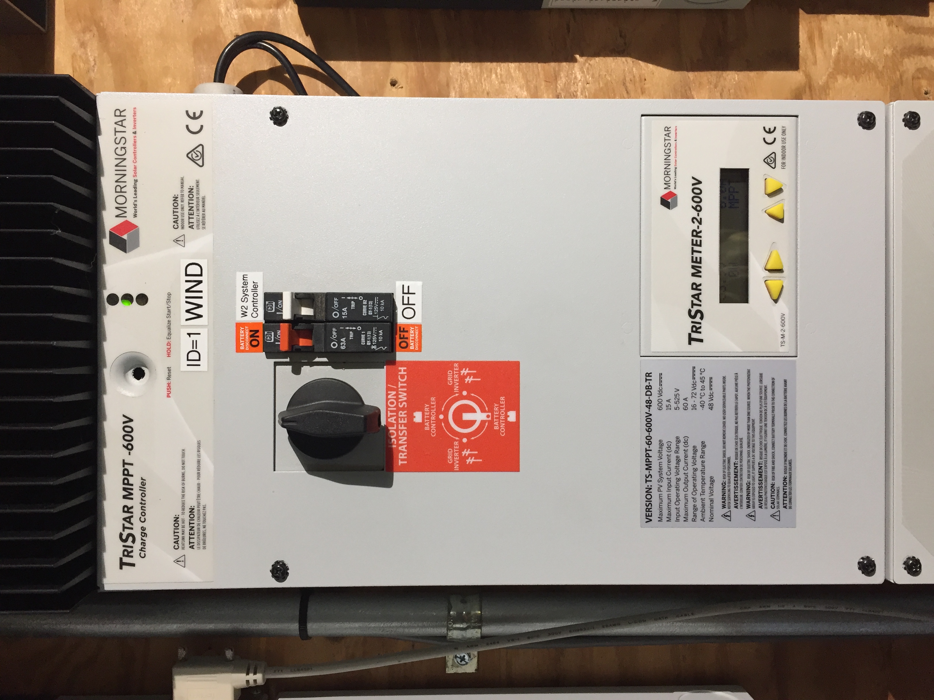 |
Click here for the latest firmware and software available for the TS-MPPT-600V.
Table 1. TS-MPPT-600V Settings
| Units | Comments | ||
|---|---|---|---|
| DIP Switches | 1 0 0 1 1 1 0 1 | - | Refer to charge controller manual for DIP switch function. |
| Hardware Version | v01.01 | - | |
| Software Version | v19 | - | |
| Mode | Wind Charge | - | |
| Regulation Voltage | 15.00 (= 60.00) | V | This controller must always operate in MPPT mode, so Reg Voltage is set higher than it should ever reach under normal operating conditions. |
| Temperature Compensation | 0.000 | V/°C | Temp comp is not necessary for lithium ion batteries. |
| Absorption Time | 1:00:00 | h:m:s | When Float Voltage is disabled (see below) and Absorption Time is complete, the charging voltage remains constant = Regulation Voltage. |
| Absorption Ext. Voltage | disabled | V | |
| Battery Service Reminder | disabled | days | |
| Float Voltage | disabled | V | |
| Equalize Voltage | disabled | V | |
| High Voltage Disconnect (HVD) | 13.88 (= 55.52) | V | 55.52/16 = 3.470V/cell, ~100% SOC per 200Ah GBS cell discharge curve. |
| HVD Reconnect | 13.31 (= 53.24) | V | 53.24/16 = 3.328V/cell, ~99% SOC. |
| Max. Regulation Limit | 14.06 (= 56.25) | V | |
| Max. Battery Current | 0.00 | A | A value of 0.00 means there's no current limit (other than controller max). |
| Array Voltage Fixed Target | disabled | V | |
| LED G to G/Y | 13.31 (= 53.24) | V | 53.24/16 = 3.328V/cell, ~99% SOC per 200Ah GBS cell discharge curve. Note that 53.24V is also the HVDR setting. |
| LED G/Y to Y | 13.21 (= 52.84) | V | 52.84/16 = 3.303V/cell, ~98% SOC. |
| LED Y to Y/R | 13.06 (= 52.25) | V | 52.25/16 = 3.266V/cell, ~85% SOC. |
| LED Y/R to R | 13.01 (= 52.03) | V | 52.03/16 = 3.252V/cell, ~75% SOC. |
| Modbus ID | 1 | - | The ID must be unique for each Modbus device in the W2 System. |
| DHCP enabled | true | - | This should change to false as soon as we implement Modbus/TCP and need an unchanging IP for the controller. There should also be another parm for the assigned IP address. |
| HTTP TCP Port | 80 | - | |
| Modbus TCP Port | 502 | - | |
| IP Bridging Enabled | false | - | Explain what this is. |
| Ethernet Power Save Mode | false | - | Explain what this is and why we're not using it. |
Table 2. TS-MPPT-600V Wind Power-Voltage Curve Settings
| Point # | Parameter name | Programmed Voltage (V) | Parameter name | Desired Power (W) | Programmed Power (W) |
|---|---|---|---|---|---|
| 1 | PV_V_0 | 120 | PV_P_0 | 5 | 3 |
| 2 | PV_V_1 | 132 | PV_P_1 | 28 | 18 |
| 3 | PV_V_2 | 144 | PV_P_2 | 68 | 44 |
| 4 | PV_V_3 | 156 | PV_P_3 | 119 | 77 |
| 5 | PV_V_4 | 168 | PV_P_4 | 184 | 120 |
| 6 | PV_V_5 | 180 | PV_P_5 | 264 | 172 |
| 7 | PV_V_6 | 192 | PV_P_6 | 360 | 234 |
| 8 | PV_V_7 | 204 | PV_P_7 | 475 | 309 |
| 9 | PV_V_8 | 216 | PV_P_8 | 608 | 395 |
| 10 | PV_V_9 | 228 | PV_P_9 | 762 | 496 |
| 11 | PV_V_10 | 240 | PV_P_10 | 939 | 610 |
| 12 | PV_V_11 | 252 | PV_P_11 | 1138 | 740 |
| 13 | PV_V_12 | 264 | PV_P_12 | 1363 | 886 |
| 14 | PV_V_13 | 276 | PV_P_13 | 1614 | 1049 |
| 15 | PV_V_14 | 288 | PV_P_14 | 1892 | 1230 |
| 16 | PV_V_15 | 300 | PV_P_15 | 2200 | 1430 |
Note
In the table above, the voltage and power values (P-V curve) programmed into the TS-MPPT-600V correspond to the following Controller operating parameters for the High voltage diversion load (HVDL): RDL = 18Ω, Vstart = 120V, Vspan = 180V, and Pmax = 2200W. See High voltage diversion load (HVDL) for the equations used to calculate the table values. As described in this Morningstar technical bulletin, application of a “calibration factor” = 0.65 to the desired output power is required to generate the power values programmed into the TS-MPPT-600V.
Caution
Making changes to the turbine P-V curve in the TS-MPPT-600V controller and/or to the Controller operating parameters for the HVDL is not recommended without technical guidance from WWE as well as familiarity with Morningstar interface software. Permanent damage to W2 System components could result from mis-set parameters.
To make changes to the programmed P-V curve:
(1) Put the turbine into Shutdown State = 1, (2) disconnect the 3-wire RS-485 (green) connector from the Controller logic board, (3) connect a RS-485 to USB adapter cable between the W2 controller and a laptop, (4) run MS-VIEW and connect to the TS-MPPT-600V (comm parameters will vary according to the particular installation), (5) edit the P-V table as described in this Morningstar technical bulletin, (6) save the changes to the TS-MPPT-600V, (7) disconnect the RS-485 to USB cable, reconnect the logic board RS-485 connector, and power cycle the TS-MPPT-600V using the (orange) Battery Disconnect breaker on its front panel. Changes to TS-MPPT-600V programming should be made only after testing the turbine with HVDL Active = 1 with a new set of Controller operating parameters (RDL, Vstart, Vspan, and Pmax) and calculating P-V curve values therefrom (a simple spreadsheet is useful for this). For proper turbine operation, the load imposed by the TS-MPPT-600V should be identical to that imposed by the HVDL.
Caution
Ground fault protection for small wind systems may be required by applicable codes. A Morningstar Ground Fault Protection Device is an option for the TS-MPPT-600V controller which has been verified to work with the W2 System.
Note
The typical market application for the TS-MPPT-600V is to redirect high-voltage PV from a battery-less, grid-connected solar inverter to battery storage. The W2 System is compatible with this usage subject to 60A/~3kW limits of a single charge controller. Interfacing grid-connected PV systems larger than ~3kW with the W2 System may require multiple 600V charge controllers and additional battery capacity.
This diversion controller is a required system component which diverts excess battery charging current to the Low voltage diversion load (LVDL). As such, it protects against battery overcharging and prevents over-voltage faults in Morningstar charge controllers. In the event of a grid outage (no inverter sell-back) with a fully-charged battery, the diversion controller will allow the W2 turbine to continue normal operation. In installations with optional PV, a second diversion controller (and LVDL) is included to allow diversion of 100% of maximum (wind + PV) input power.
The TS-M-2 meter shown in the photo is optional.
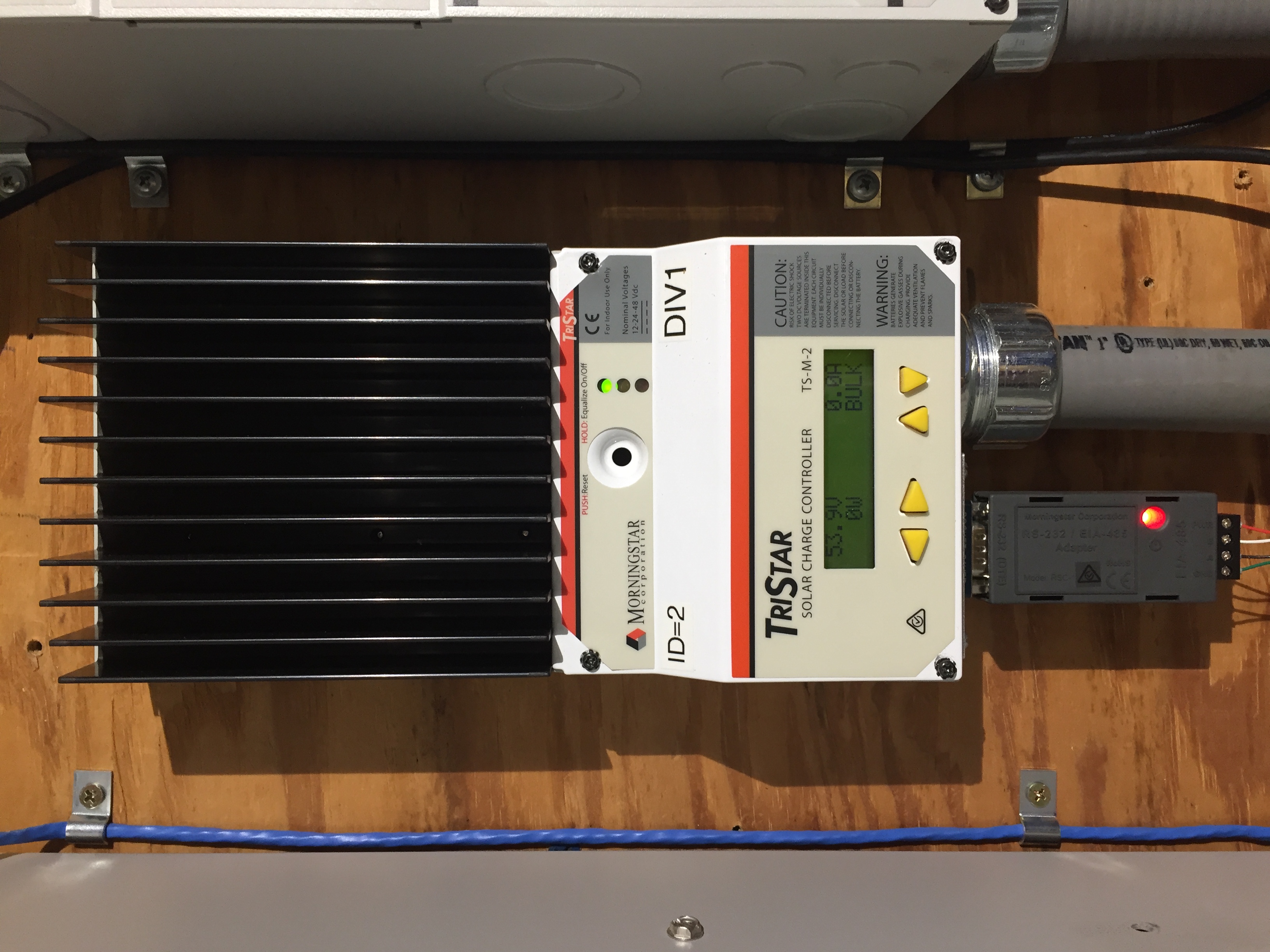 |
Click here for the latest firmware and software available for the TS-60.
Table 3. TS-60 Settings
| Units | Comments | ||
|---|---|---|---|
| DIP Switches | 1 1 1 1 1 1 1 0 | - | Refer to charge controller manual for DIP switch function. |
| Hardware Version | v01.04 | - | |
| Software Version | v14 | - | |
| Mode | Diversion | - | |
| Modbus ID | 2 | - | The ID must be unique for each Modbus device in the W2 System. |
| Regulation Voltage | 13.75 (= 55.00) | V | This is set 1.0V higher than the Radian-series Inverter Sell voltage (54.0). |
| Temperature Compensation | 0.00 | V/°C | Temp comp is not necessary for lithium ion batteries. |
| LED G to G/Y | 13.31 (= 53.24) | V | 53.24/16 = 3.328V/cell, ~99% SOC per 200Ah GBS cell discharge curve. Note that 53.24V is the HVDR setting of the TS-MPPT-30 and TS-MPPT-60 PV charge controllers. |
| LED G/Y to Y | 13.21 (= 52.84) | V | 52.84/16 = 3.303V/cell, ~98% SOC. |
| LED Y to Y/R | 13.06 (= 52.24) | V | 52.25/16 = 3.266V/cell, ~85% SOC. |
| LED Y/R to R blink | 13.01 (= 52.04) | V | 52.03/16 = 3.252V/cell, ~75% SOC. |
This charge controller (photo, right) is an optional device used to control up to 30A of PV input. Power conductors to and from this controller originate in the load center (GSLC) of the Outback Radian-series Inverter. The TS-MPPT-30 requires an EIA-485/RS-232 adapter (RSC-1) (see photo bottom) for its Modbus/RTU (EIA-485) connection with the W2 turbine controller.
The TS-M-2 meter shown in the photo is optional.
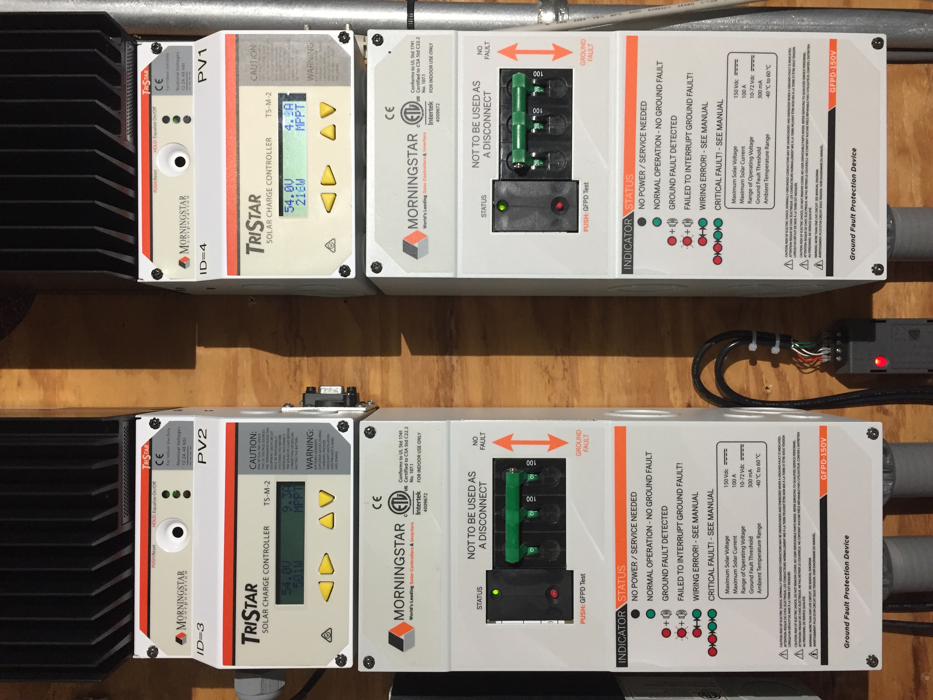 |
Click here for the latest firmware and software available for the TS-MPPT-30.
In the table below, TS-MPPT-30 firmware settings are based on guidance from several sources for optimal LiFePO4 battery charging. A key feature is the use of the High Voltage Disconnect (HVD) and HVD Reconnect (HVDR) parameters to act as a ON-OFF switch to control PV charging during off-grid operation (no inverter sell-back). The intent is to avoid a constant-voltage “float” state which may shorten battery life.
Table 4. TS-MPPT-30 Settings
| Units | Comments | ||
|---|---|---|---|
| DIP Switches | 0 1 1 1 1 1 0 0 | - | Refer to charge controller manual for DIP switch function. |
| Hardware Version | v01.01 | - | |
| Software Version | v29 | - | |
| Mode | Solar Charge | - | |
| Regulation Voltage | 14.00 (= 56.00) | V | |
| Temperature Compensation | 0.000 | V/°C | Temp comp is not necessary for lithium ion batteries. |
| Absorption Time | 1:00:00 | h:m:s | When Float Voltage is disabled (see below) and Absorption Time is complete, the charging voltage remains constant = Regulation Voltage. |
| Absorption Ext. Voltage | disabled | V | |
| Battery Service Reminder | disabled | days | |
| Float Voltage | disabled | V | |
| Equalize Voltage | disabled | V | |
| High Voltage Disconnect (HVD) | 13.88 (= 55.52) | V | 55.52/16 = 3.470V/cell, ~100% SOC per 200Ah GBS cell discharge curve. |
| HVD Reconnect | 13.31 (= 53.24) | V | 53.24/16 = 3.328V/cell, ~99% SOC. |
| Max. Regulation Limit | 14.06 (= 56.25) | V | |
| Max. Battery Current | 0.00 | A | A value of 0.00 means there's no current limit (other than controller max). |
| Array Voltage Fixed Target | disabled | V | |
| LED G to G/Y | 13.31 (= 53.24) | V | 53.24/16 = 3.328V/cell, ~99% SOC per 200Ah GBS cell discharge curve. Note that 53.24V is also the HVDR setting. |
| LED G/Y to Y | 13.21 (= 52.84) | V | 52.84/16 = 3.303V/cell, ~98% SOC. |
| LED Y to Y/R | 13.06 (= 52.25) | V | 52.25/16 = 3.266V/cell, ~85% SOC. |
| LED Y/R to R | 13.01 (= 52.03) | V | 52.03/16 = 3.252V/cell, ~75% SOC. |
| Modbus ID | 4 | - | The ID must be unique for each Modbus device in the W2 System. |
| DHCP enabled | true | - | This should change to false as soon as we implement Modbus/TCP and need an unchanging IP for the controller. There should also be another parm for the assigned IP address. |
| HTTP TCP Port | 80 | - | |
| Modbus TCP Port | 502 | - | |
| IP Bridging Enabled | false | - | Explain what this is. |
| Ethernet Power Save Mode | false | - | Explain what this is and why we're not using it. |
This charge controller (photo, left) is an optional device used to control up to 60A of PV input. Power conductors to and from this controller originate in the load center (GSLC) of the Outback Radian-series Inverter. While Modbus/TCP (Ethernet) could be used with this device, testing revealed that Modbus/RTU (EIA-485) was faster.
The TS-M-2 meter shown in the photo is optional.
 |
Click here for the latest firmware and software available for the TS-MPPT-60.
In the table below, TS-MPPT-60 firmware settings are based on guidance from several sources for optimal LiFePO4 battery charging. A key feature is the use of the High Voltage Disconnect (HVD) and HVD Reconnect (HVDR) parameters to act as a ON-OFF charging switch. The intent is to avoid a constant-voltage “float” state which may shorten battery life.
Table 5. TS-MPPT-60 Settings
| Parameter | Value | Units | Comments |
|---|---|---|---|
| DIP Switches | 0 1 1 1 1 1 0 0 | - | Refer to charge controller manual for DIP switch function. |
| Hardware Version | v01.01 | - | |
| Software Version | v32 | - | |
| Mode | Solar Charge | - | |
| Regulation Voltage | 14.00 (= 56.00) | V | |
| Temperature Compensation | 0.000 | V/°C | Temp comp is not necessary for lithium ion batteries. |
| Absorption Time | 1:00:00 | h:m:s | When Float Voltage is disabled (see below) and Absorption Time is complete, the charging voltage remains constant = Regulation Voltage. |
| Absorption Ext. Voltage | disabled | V | |
| Battery Service Reminder | disabled | days | |
| Float Voltage | disabled | V | |
| Equalize Voltage | disabled | V | |
| High Voltage Disconnect (HVD) | 13.88 (= 55.52) | V | 55.52/16 = 3.470V/cell, ~100% SOC per 200Ah GBS cell discharge curve. |
| HVD Reconnect | 13.31 (= 53.24) | V | 53.24/16 = 3.328V/cell, ~99% SOC. |
| Max. Regulation Limit | 14.06 (= 56.25) | V | |
| Max. Battery Current | 0.00 | A | A value of 0.00 means there's no current limit (other than controller max). |
| Array Voltage Fixed Target | disabled | V | |
| LED G to G/Y | 13.31 (= 53.24) | V | 53.24/16 = 3.328V/cell, ~99% SOC per 200Ah GBS cell discharge curve. Note that 53.24V is also the HVDR setting. |
| LED G/Y to Y | 13.21 (= 52.84) | V | 52.84/16 = 3.303V/cell, ~98% SOC. |
| LED Y to Y/R | 13.06 (= 52.25) | V | 52.25/16 = 3.266V/cell, ~85% SOC. |
| LED Y/R to R | 13.01 (= 52.03) | V | 52.03/16 = 3.252V/cell, ~75% SOC. |
| Modbus ID | 3 | - | The ID must be unique for each Modbus device in the W2 System. |
| DHCP enabled | true | - | This should change to false as soon as we implement Modbus/TCP and need an unchanging IP for the controller. There should also be another parm for the assigned IP address. |
| HTTP TCP Port | 80 | - | |
| Modbus TCP Port | 502 | - | |
| IP Bridging Enabled | false | - | Explain what this is. |
| Ethernet Power Save Mode | false | - | Explain what this is and why we're not using it. |
Morningstar controllers are typically mounted adjacent to the W2 turbine controller on a dedicated wall panel. A wiring trough below the devices serves as a shared wireway for all current-carrying conductors. Morningstar controllers must be installed indoors in a non-freezing, non-condensing environment.
Caution
Ground fault protection for PV systems may be required by applicable codes. A Ground Fault Protection Device (GFPD) is an option for Morningstar controllers and has been verified to work with the W2 System. GFPD's are installed on the controllers pictured below.
 |
The HVDL is an 18Ω wirewound ceramic resistor with a continuous power rating of 2 kW. It is housed in an enclosure along with the Low voltage diversion load (LVDL). In the event of a TS-MPPT-600V controller fault, DC output from the Power board is automatically redirected to the HVDL. The HVDL can also be used as a primary load for the wind turbine by setting HVDL Active = 1 on the Controller operating parameters web page.
 |
Note
When the HVDL is active, the rectifier on the W2 controller Power board is managed by a PWM algorithm in Controller firmware to generate a Power-Voltage (P-V) load curve in real-time. This HVDL load curve should be used to set the voltage and power load curve values programmed into the TS-MPPT-600V controller according to the equations below. The result is that the wind turbine operates exactly the same whether its load is the HVDL or the Morningstar controller. The resistance of the HVDL has been chosen to closely match the internal resistance of the W2 Alternator to achieve maximum power transfer.
Caution
The four variables listed below are also Controller operating parameters which can be set on-the-fly while HVDL Active = 1 to fine tune turbine performance (e.g., by monitoring tip speed ratio). Changing any of these parameters without a full understanding of possible consequences is not recommended and could result in turbine damage or destruction!
RDL = Diversion load resistance. Default: HVDL Resistance = 18Ω.
Vstart = Turbine voltage must reach this value before any load is imposed. Default: HVDL Vstart = 120V.
Vspan = Voltage range over which D increases linearly from 0 at Vstart to Dmax at Vstart + Vspan. Default: HVDL Vspan = 180V.
Pmax = Maximum turbine power. Default: HVDL Pmax = 2200W.
The PWM algorithm sets the HVDL duty cycle (D), and therefore the diversion load power PDL, according to the following equations:
Dmax = RDL * Pmax / (Vstart + Vspan)2. This is the duty cycle at Pmax.
D = Dmax * (Vobs - Vstart) / Vspan. This is the duty cycle when Vstart ≤ Vobs ≤ Vstart + Vspan.
D = RDL * Pmax / Vobs2. This is the duty cycle when Vobs > Vstart + Vspan.
In this case, D will decrease as Vobs increases to maintain output power at Pmax.
PDL = D * Vobs2 / RDL.
The LVDL is a 1Ω wirewound ceramic resistor with a continuous power rating of 2 kW. It is mounted in a shared enclosure with the High voltage diversion load (HVDL) (see photo above). The LVDL is directly connected to the “Load” terminals of a TS-60 diversion controller.
The battery cabinet, lithium ion batteries, and battery management system (BMS) are shipped pre-wired and pre-configured from WWE. As a safety precaution, connectors (insulated copper bars) and cabling between 12V battery modules are shipped disconnected. Also, the entire battery enclosure is tightly packed with non-conductive insulating materials to prevent shifting of batteries during shipping.
Energy storage for the W2 System is provided by 16 series-connected GBS-LFMP200AHX (LiFeMnPO4, 200Ah x 3.2V = 640Wh) cells. The resulting battery “stack” has a nominal voltage of 51.2V @ 200Ah = 10.24 kWh of energy storage capacity. Charge and discharge curves provided by the battery vendor for 100Ah GBS cells were used to determine programmed settings for all Morningstar controllers.
Batteries are housed in a pre-assembled Midnite Solar MNBE-D battery enclosure pre-fitted with a 175A DC breaker, a Nuvation Low-Voltage BMS, and related power switching components (see photos below).
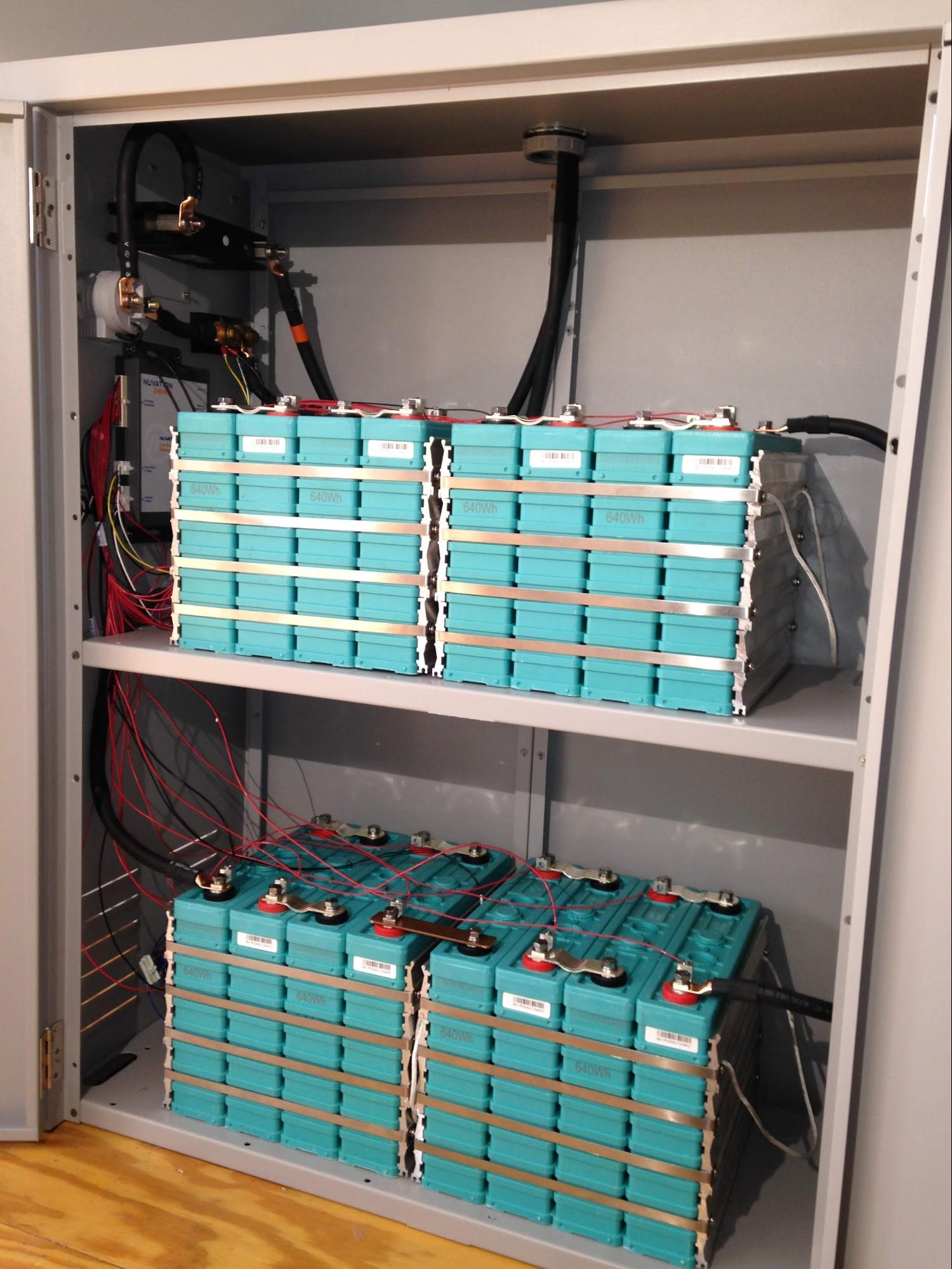 |
A 16-channel, 2-thermistor, 4-in/4-out GPIO Nuvation Low-Voltage BMS “starter kit” monitors cell voltage and temperature, and manages a main contactor, cell balancing, and battery temperature (optional, see below). A 200A/900VDC (24VDC coil) contactor for automatic (dis)connection and a shunt resistor for battery current measurement are pre-installed in the cabinet with the BMS. The small-gauge wires in the battery cabinet are mostly voltage-sense wires for individual cells (see photos and wiring diagram). The W2 turbine controller communicates with the Nuvation BMS via Modbus/TCP (blue Ethernet cable in the photo below, see Communications cabling).
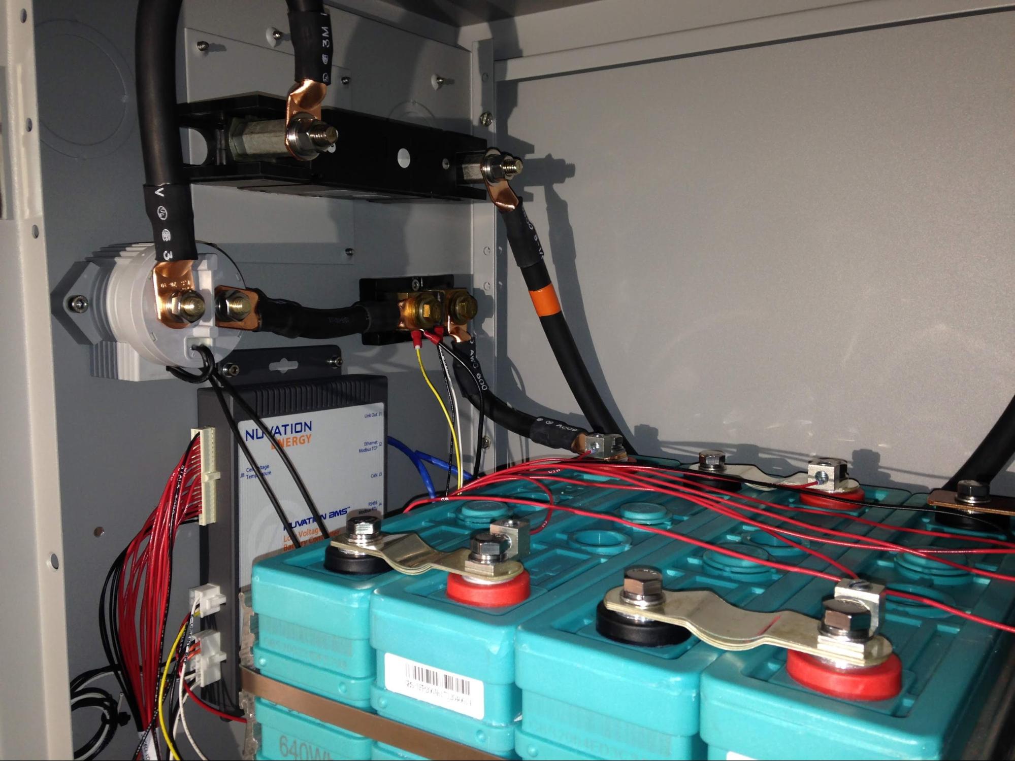 |
Optionally, battery cabinet temperature control is accomplished by two (2) silicone rubber thermal pads (SRP12241, 12in x 24in, rated @120V/360W) placed on battery enclosure shelves. Two (2) thermal pads are connected to the battery in parallel through a 20A/120VDC (48VDC coil) power relay which is controlled directly by the BMS (see photo below and wiring diagram). When heating fully-charged batteries, the thermal pads intermittently consume about (53.3V)˛ / 20Ω = 142W of power to maintain battery temperature above 8°C.
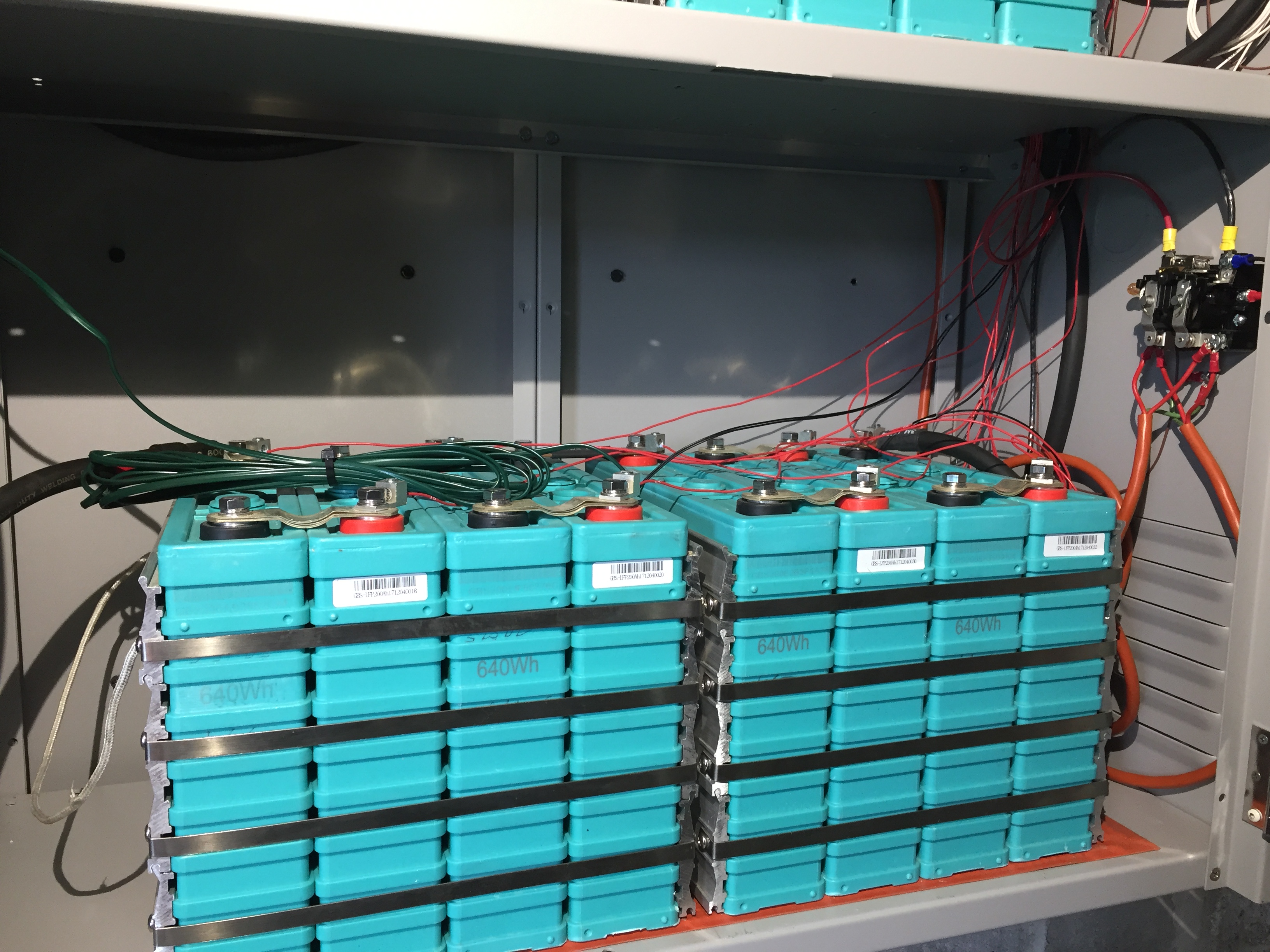 |
Tip
Proper initialization of temperature control requires that starting BMS thermistor temperatures be greater than the high temperature setpoint (typ. 11°C) in the BMS config file. This causes the high temperature limit condition to be triggered when the enclosure temperature subsequently falls below 11°C (the low setpoint is 8°C). If the batteries are installed in cold conditions, hand-warming the pair of thermistors after BMS startup will accomplish the proper initialization.
Note
A BMS configuration file created using the Nuvation BMS nCloud website with defaults for the 16-channel “starter kit” is used to initialize the BMS. WWE edits to this configuration file add user-defined trig parameters defining high and low temperature limits for the thermal pads. Battery temperature control is achieved using the modified configuration file along with “loopback” wiring connections on the General Purpose Input/Output (GPIO) connector. Refer to the modified BMS configuration file for parameter descriptions used for temperature control and to the wiring diagram for connection details.
In addition to networking with the W2 turbine controller and System monitor web page, the Nuvation BMS also provides its own user interface which can be accessed locally at IP address 192.168.1.21 (the default address can be changed). This interface allows detailed monitoring and direct control of all BMS parameters. Details are described in Nuvation technical documentation.
 |
Note
Q: What happens when stack_warn_(dis)charge_therm_lo.thresh (typ. 5°C) is reached? When that occurs, the BMS interface webpage indicates that both the charge and discharge "Current Limit" are 0A. Really zero? In that case, will any charge or discharge current (and there is always some) trigger a battery disconnect? Actual observations suggest the answer is yes! This concern was the motivation for using the pair of user-defined thermistor trig registers (instead of the pre-defined warn registers) to define an independent temperature control range for the thermal pads.
Two inverters have been tested with the W2 System – the Outback Radian-series and Outback FXR3048A.
In the W2 System, an Outback Radian-series GS4048A (4kW) or GS8048A (8kW) inverter is paired with an Outback GSLC 175-120/240 load center (see photos below). The GSLC houses DC busbars and breakers for power distribution among components of the W2 System. It also contains AC busbars and breakers for grid input (or sell-back), generator input (if any), and inverter output to backup loads. Refer to the W2 System wiring diagram for details.
 |
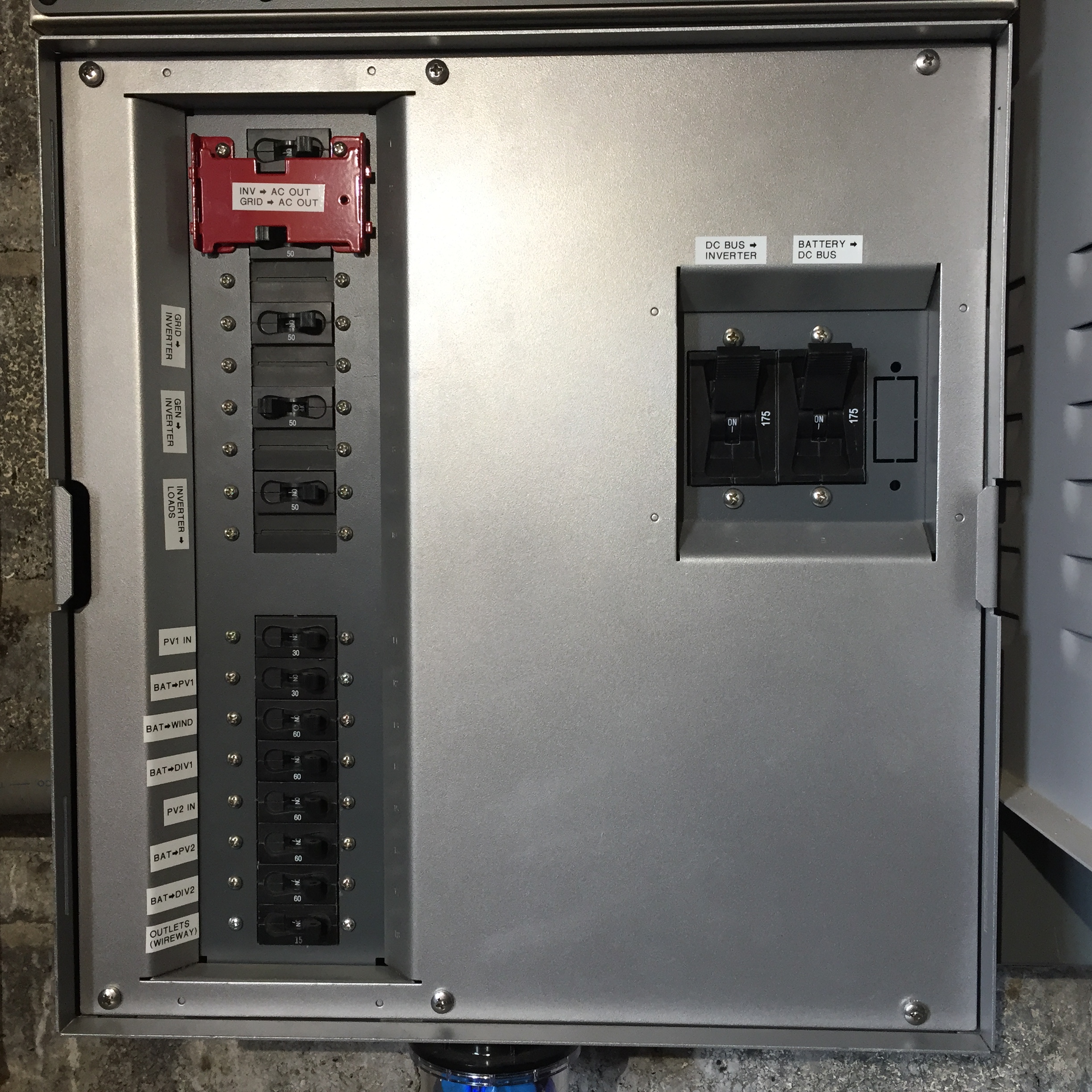 |
An Outback Mate3s system display and controller is included with the W2 System to monitor inverter status and manipulate inverter operating parameters dynamically and independently of the W2 controller user interface. A web-based user interface for remote monitoring and programming the Mate3s and GS inverter is also available via a Outback service called OpticsRE.
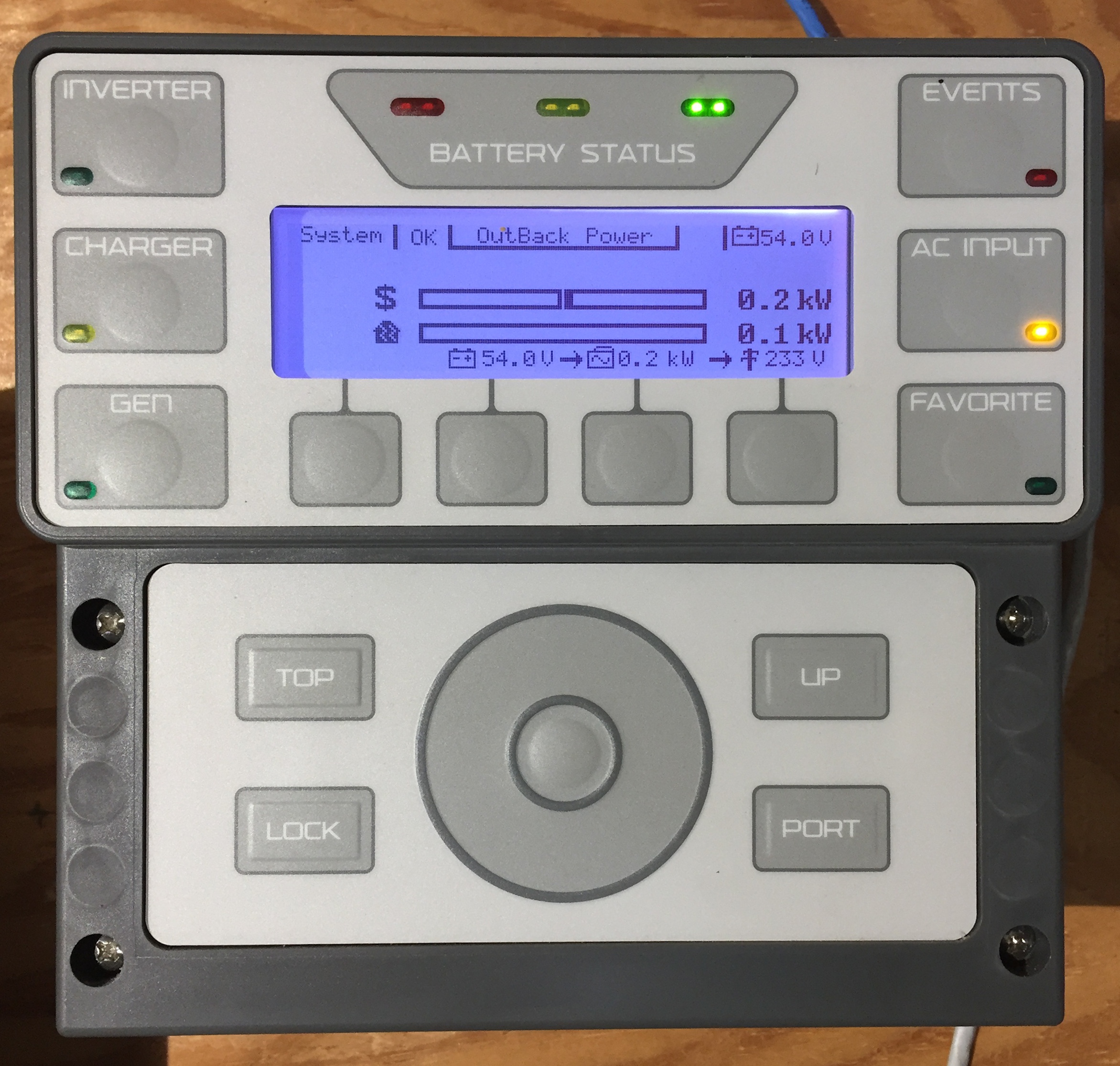 |
Note
Optional expansion of the W2 System can add “stacked” GS8048A inverters up to a limit of 32 kW of inverter output power. Additional battery capacity is also required to support larger loads expected with expanded inverter capacity.
The Outback FXR3048A inverter was the first inverter tested with the W2 System. It was paired with a MidNite Solar MNE125AL-PLUS E-Panel for Outback as an AC/DC load center analogous to the Outback Radian GSLC. Further development of this system was discontinued in favor of the better integration and output power of the GS4048A+GSLC or GS8048A+GSLC system.
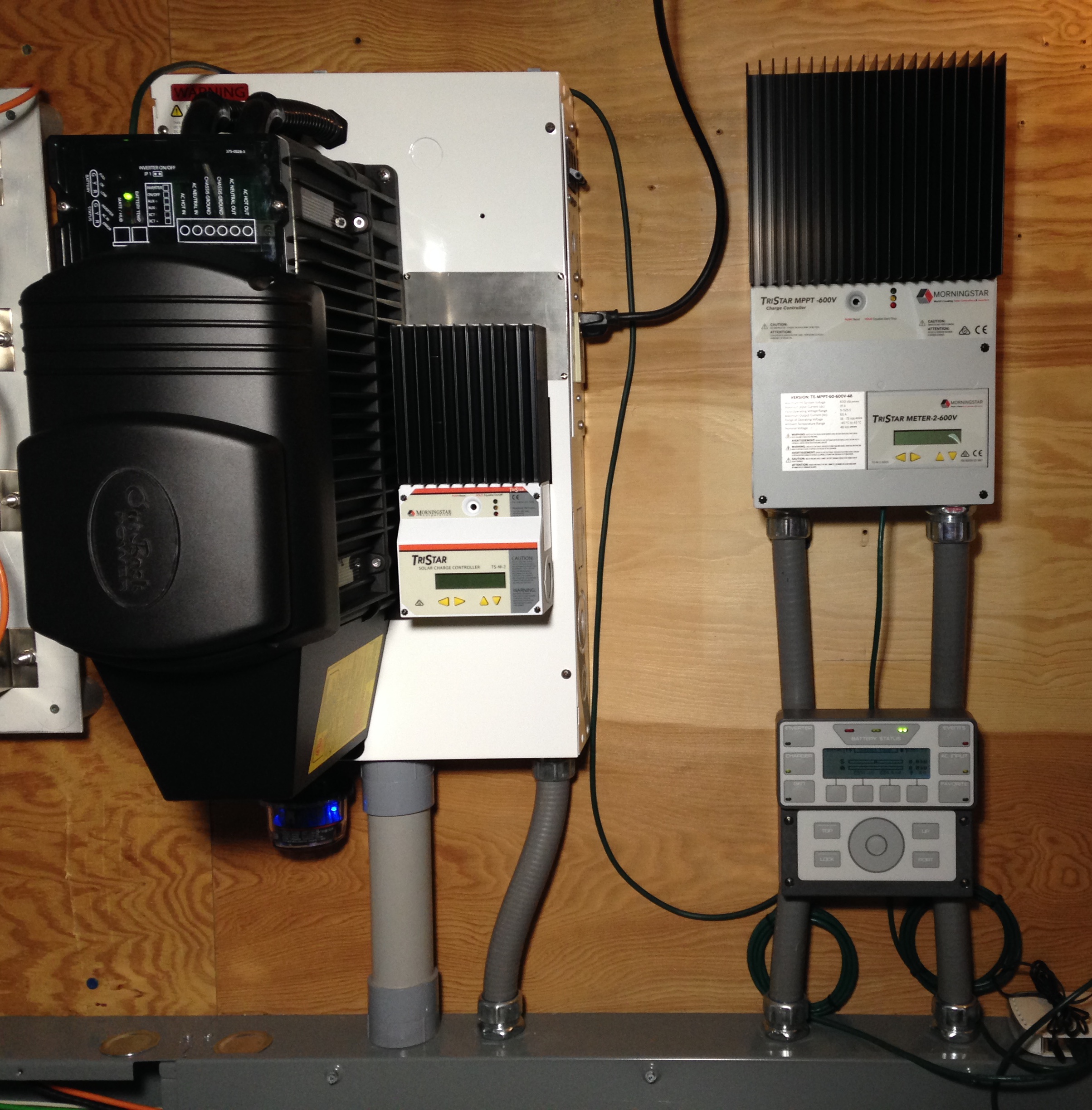 |
PV battery charging is an option for the W2 System.
The photo below shows an array of three (3) Panasonic HIT 320W modules successfully used with a rotate-able, tilt-able mounting rack designed by WWE for the Legacy tower. DC wiring from the modules is routed to a tower-mounted PV combiner (e.g., Outback FWPV4-FH600) and from there into the same tower base junction box which accepts the turbine tower cable (see photo). Charge control is provided by a TS-MPPT-30 PV controller networked with the W2 System.
Note
A design update to the original PV rack will be lighter, better balanced, and easier to assemble and manipulate.
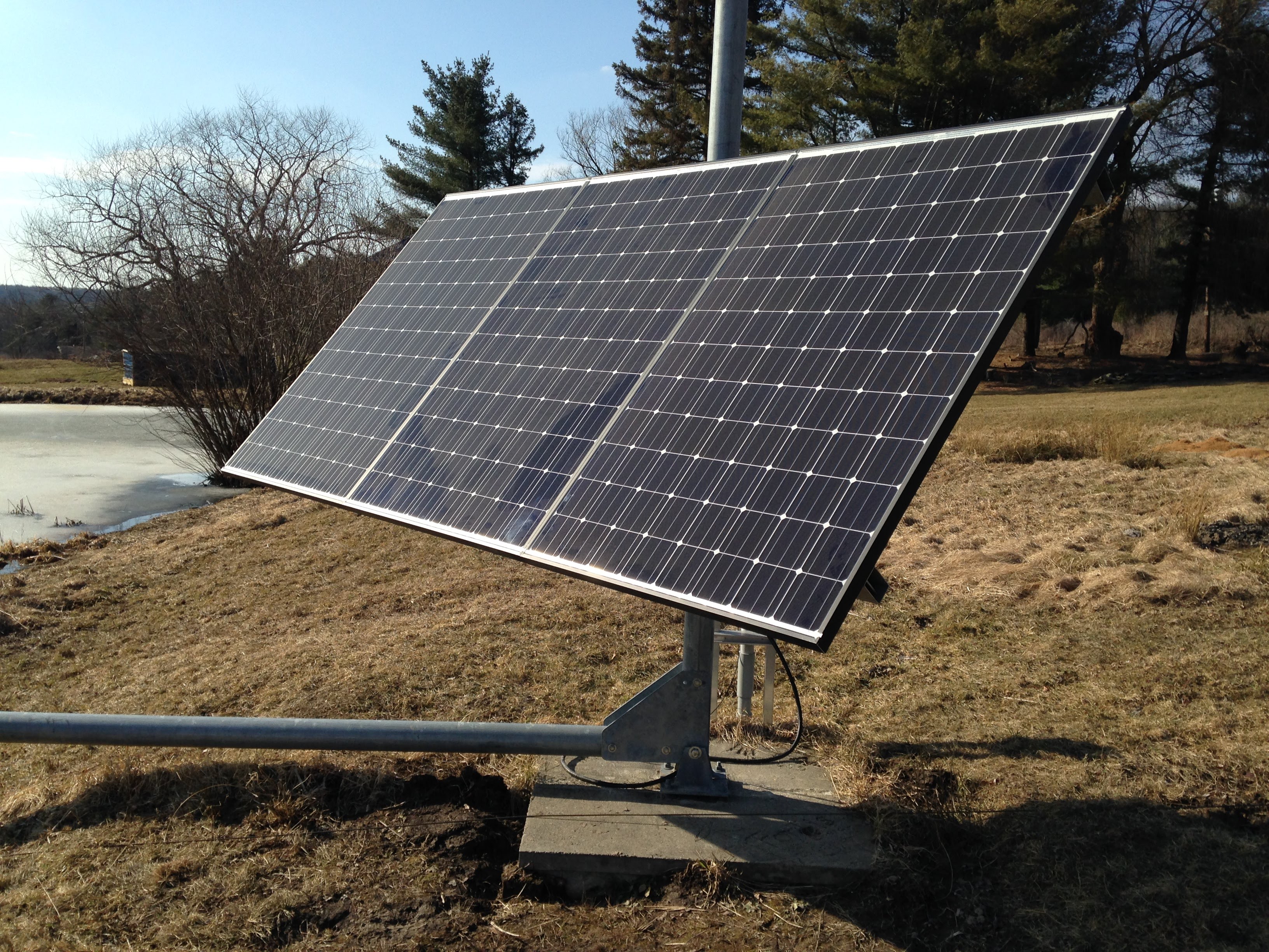 |
 |
The Controller operating parameters web page sets IP addresses for a Data Server and an Update Server as well as an Update Port for the latter. The Data Server and Update Server may run on the same physical machine. For the W2 development system, this was an iMac desktop running MacOS 10.13.6 (High Sierra). The setup instructions given below pertain only to that platform and are provided in the event that someone wishes to set up their own W2 System server(s).
W2 system data collected by a W2 turbine controller are sent as UDP packet streams from the controller to Data Server ports 58328, 58329, 58330, and 58332. The data are processed by continuously running Python scripts and stored as daily log files on the server. The UDP data are tagged with the MAC address of the source controller so that the server can process data streams from many controllers (W2 system sites, turbine sites) simultaneously. The Data Server also runs an Apache webserver (utilizing PHP scripts to access the log files) which provides a user interface to streaming (real time) and historical data for specific W2 systems.
The Data Server continuously runs several Python scripts to receive and process UDP data packets from one or more controllers directed to ports 58328-58332, as well as data from one or more Outback Mate3s devices directed to port 57027. Port Forwarding must be set up for ports 58328-58332 on the local router to direct these UDP packets (typically coming from the outside world, WAN) to the server's local (LAN) IP address. For security reasons, many routers do not allow LAN broadcasting (for example, to 192.168.1.255), so if the server's LAN address changes, be sure to also change the router's Port Forwarding information. The Data Server IP address must be programmed separately into Outback Mate3S device under System Configuration — Data Stream — Destination IP (see Mate3S Programming Guide); unfortunately, there appears to be no way to change the Destination IP address remotely (for example, via the OpticsRE web interface).
$ ls -l ~/Sites/WWE/bin/udp
-rw-r--r--  1 WWE  staff    1222 Sep  6 19:08 README
drwxr-xr-x  3 WWE  staff      96 Sep  7 15:56 __pycache__
-rw-r--r--  1 WWE  staff     392 Sep  6 19:08 macs2sites.py
-rw-r--r--  1 WWE  staff     432 Sep  7 15:49 macs2sites.pyc
-rw-r--r--  1 WWE  staff     342 Sep  7 18:12 udp-client-test.py
-rw-r--r--  1 WWE  staff       0 Sep  7 18:33 udp-client-test.stderr
-rw-r--r--@ 1 WWE  staff    8399 Sep  7 18:12 udp-config.py
-rw-r--r--  1 WWE  staff       0 Sep  7 18:32 udp-config.stderr
-rw-r--r--  1 WWE  staff  393621 Sep  8 20:04 udp-config.stdout
-rw-r--r--@ 1 WWE  staff    3561 Sep  7 18:12 udp-controller.py
-rw-r--r--  1 WWE  staff       0 Sep  7 18:15 udp-controller.stderr
-rw-r--r--@ 1 WWE  staff    3565 Sep  7 18:12 udp-modbus-fast.py
-rw-r--r--  1 WWE  staff       0 Sep  7 18:30 udp-modbus-fast.stderr
-rw-r--r--@ 1 WWE  staff    3569 Sep  7 18:12 udp-modbus-slow.py
-rw-r--r--  1 WWE  staff       0 Sep  7 18:31 udp-modbus-slow.stderr
-rw-r--r--@ 1 WWE  staff    3570 Sep  7 18:12 udp-nuvation.py
-rw-r--r--  1 WWE  staff       0 Sep  7 18:31 udp-nuvation.stderr
-rw-r--r--@ 1 WWE  staff    5441 Sep  7 18:12 udp-outback.py
-rw-r--r--  1 WWE  staff       0 Sep  7 18:32 udp-outback.stderr
-rw-r--r--  1 WWE  staff     291 Sep  7 18:12 udp-server-test.py
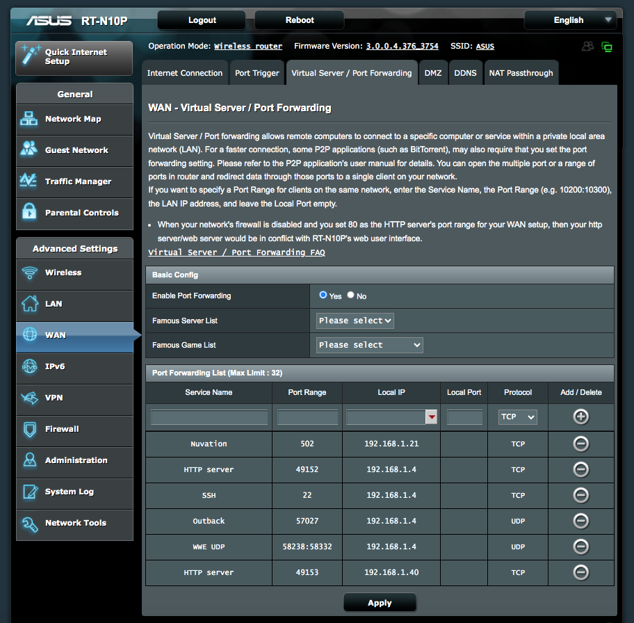 |
The Python scripts are managed by plist files that execute on MacOS boot up and restart automatically if killed for any reason:
$ ls -l /Library/LaunchDaemons/com.wwe*
-rwxr-xr-x  1 root  wheel  789 Sep  7 18:26 /Library/LaunchDaemons/com.wwe.udp-client-test.plist
-rwxr-xr-x  1 root  wheel  849 Sep  7 18:25 /Library/LaunchDaemons/com.wwe.udp-config.plist
-rwxr-xr-x  1 root  wheel  817 Sep  7 17:20 /Library/LaunchDaemons/com.wwe.udp-controller.plist
-rwxr-xr-x  1 root  wheel  820 Sep  7 18:24 /Library/LaunchDaemons/com.wwe.udp-modbus-fast.plist
-rwxr-xr-x  1 root  wheel  820 Sep  7 18:24 /Library/LaunchDaemons/com.wwe.udp-modbus-slow.plist
-rwxr-xr-x  1 root  wheel  811 Sep  7 18:23 /Library/LaunchDaemons/com.wwe.udp-nuvation.plist
-rwxr-xr-x  1 root  wheel  815 Sep  7 18:22 /Library/LaunchDaemons/com.wwe.udp-outback.plist
Once launched, a listing of running Python UDP processes should look something like this:
$ ps x | grep -i python.*udp
85732   ??  Ss     1:38.65 /usr/bin/python /Users/WWE/Sites/WWE/bin/udp/udp-controller.py
88410   ??  Ss     1:37.95 /usr/bin/python /Users/WWE/Sites/WWE/bin/udp/udp-modbus-fast.py
88588   ??  Ss     0:00.08 /usr/bin/python /Users/WWE/Sites/WWE/bin/udp/udp-modbus-slow.py
88695   ??  Ss     1:22.41 /usr/bin/python /Users/WWE/Sites/WWE/bin/udp/udp-nuvation.py
88844   ??  Ss     0:24.98 /usr/local/bin/python3 /Users/WWE/Sites/WWE/bin/udp/udp-outback.py
88973   ??  Ss     0:01.45 /usr/local/bin/python3 /Users/WWE/Sites/WWE/bin/udp/udp-config.py
Wind turbine controller data are packaged by the controller into UDP packets and directed to port 58328 on the Data Server about once per second. These UDP packets are processed by the udp-controller.py script which is invoked by com.wwe.udp-controller.plist. The Python script writes a JSON-formatted data line at the same rate to a log file: SITENAME.yyyy.mm.dd.log.
Morningstar charge controller Modbus/RTU “fast” data are packaged by the controller into UDP packets and directed to port 58329 on the Data Server about once per second. These UDP packets are processed by the udp-modbus-fast.py script which is invoked by com.wwe.udp-modbus-fast.plist. The Python script writes a JSON-formatted data line at the same rate to a log file: SITENAME.yyyy.mm.dd.mod.log.
Morningstar charge controller Modbus/RTU “slow” data are packaged by the controller into UDP packets and directed to port 58330 on the Data Server about once per hour. These UDP packets are processed by the udp-modbus-slow.py script which is invoked by com.wwe.udp-modbus-slow.plist. The Python script writes a JSON-formatted data line at the same rate to a log file: SITENAME.yyyy.mm.dd.modslow.log.
Nuvation battery management system (BMS) Modbus/TCP data are packaged by the controller into UDP packets and directed to port 58332 on the Data Server about once per second. These UDP packets are processed by the udp-nuvation.py script which is invoked by com.wwe.udp-nuvation.plist. The Python script writes a JSON-formatted data line at the same rate to a log file: SITENAME.yyyy.mm.dd.nuvation.log.
The udp-outback.py script, invoked by com.wwe.udp-outback.plist, handles a pre-formatted UDP data stream from the Outback Mate3s System Display and Controller, directed to port 57027 of the Data Server about once per second. The script writes a JSON-formatted data line at the same rate to a log file: SITENAME.yyyy.mm.dd.outback.log.
The macs2sites.py script contains a data object called mac2site which matches W2 System site names to unique WWE controller and Outback Mate3s Ethernet MAC addresses. This object is imported by the various udp-something.py scripts.
The user interface to a specific W2 System is a web page served from the Data Server (running Apache on port 49152). The System Monitor is intended to be a comprehensive dashboard-type monitor for an entire W2 System. It is updated as bugs are fixed and new features are added. The display mode and a unique W2 System site name are specified in the URL query string. For example: http://192.168.1.4:49152/WWE/monitor/system2a.html?site=WINDLABR3&mode=realtime.
The system monitor web page calls various PHP scripts to access system-specific log files (described above) saved on the server by Python scripts. This web page integrates data from the turbine controller, Morningstar charge controllers, Nuvation BMS, Outback inverter(s), and other external resources. Refer to this example /etc/apache2/httpd.conf configuration file for Apache setup details.
The getlog.php script processes native controller data from a server log file.
The getmodlog.php script processes Modbus (Morningstar) data from a server log file.
The getnuvation.php script processes Nuvation BMS data saved from a server log file.
The getoutback.php script processes Outback (Mate3S, Radian inverter) data from a server log file.
Hopefully, information displayed on the page is clear and usage is largely intuitive. More information about a data table item is displayed when the mouse pointer hovers over the item value (not the item name). Each data table item that is checked is plotted in a color matching that of its checkbox background. Checkboxes with a white background and black checkmark – ☑ – are plotted invisibly. The purpose of this is to make past values of these (often non-numeric) data items available for inspection in the tables when the user moves the mouse over the plot area. Unchecked data items are not plotted and so will not show data values when the mouse is moved over the plot area.
Tip
The System Monitor is useful during installation, commissioning, and maintenance of the various W2 System components. As such, an effort should be made to get it up-and-running prior to physical installation of a W2 system at a new site.
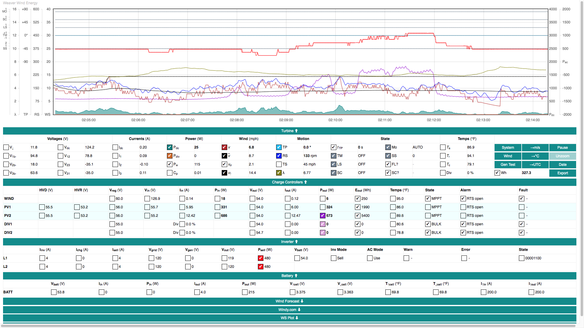 |
The Update Server updates system configuration (via UDP requests into port 58331) and is also the source of Firmware updates (via HTTP requests to the specified Update Port). As previously noted, the Update Server and the Data Server may reside on the same physical machine.
W2 System configuration data (a subset of Controller operating parameters) are sent from the controller in a UDP packet directed to port 58331 on the Update Server once per Update Interval minutes. The server compares the current controller configuration against a server copy. Discrepancies (if any) are either communicated back to the controller or written to the server depending on the state of the Override Updates? parameter. The configuration data UDP packet is processed by the udp-config.py script which is invoked by com.wwe.udp-config.plist.
Note
When the Controller operating parameters web form is submitted, user-updated parameters are sent immediately from the Data Server to the controller – and also take effect immediately. If Override Updates? = 1, user-updated parameters will saved to the Data Server within Update Interval minutes. However, if Override Updates? = 0, the server will revert user changes to the server version (with some exceptions noted below). System configuration is handled this way to allow recovery from loss or corruption of configuration data in controller memory and/or on the controller SD card.
The udp-config.py script on the Update Server compares controller parameters against the server's copy except for the following: Shutdown State, Override Updates?, HVDL Active, PV1 Disconnect, PV2 Disconnect, and Restart Count. As long as Override Updates? = 0, these exceptions allow the system operator to dynamically control important system power flow parameters without the possibility of corrupting other parameters. For this reason, WWE recommends leaving Override Updates? = 0 until the system operator fully understands the consequences of changing any operating parameter.
A firmware update is triggered whenever the controller's firmware binary file name (Update File parameter) differs from the name in the system configuration file on the Update Server. As described in System configuration, controller configuration is checked against Update Server configuration every Update Interval minutes. In order to receive firmware updates from the Update Server, the Override Updates? parameter must be set = 0.
Whenever the controller sees that a new firmware file is available, a bootloader program called updatefw.bin is downloaded from the Update Server at Update Port and is loaded into Arduino flash memory (at FLASH1). The controller then reboots and runs the bootloader which downloads a new firmware binary file from the Update Server into Arduino flash memory (at FLASH0). The controller reboots again and executes the new firmware version. The process takes less than one minute. This server-based update method is completely independent of the Arduino Programming Port (typically used during program development). It also allows for efficient deployment of firmware updates to zillions of controllers.
Tip
Arduino code for WWE controller firmware is available on GitHub as a public, open-source repository. The code is extensively commented and updated at irregular intervals as bugs are fixed and features are added. Its authors hope that it might serve as a platform (or inspiration) for a future generation of “smart” small wind turbines.
The W2 System may have multiple charging sources handled by separate Morningstar controllers. Power from the W2 wind turbine is managed by the W2 turbine controller. As such...
Important
Proper sequencing of shutdown and startup steps is important in order to avoid unexpected electrical loading or unloading of the turbine and other system components.
Warning
Take these actions ONLY if there is imminent danger to persons or property due to fire or other emergency. Do NOT put yourself in danger in an attempt to perform these steps!
Turn TURBINE BRAKE switch ON (UP) – labeled WIND TURBINE BRAKE. The Brake switch is usually located at the tower base, but may also be found anywhere along the wiring path from the tower to the indoor balance-of-system.
Turn PV INPUT breaker(s) OFF – labeled PV1 IN, PV2 IN, etc. These breakers are located in the Outback Radian load center (GSLC).
Turn BATTERY breaker OFF – labeled BATTERY. This breaker is located on the side panel of the battery enclosure.
Caution
Damage to system components is possible due to an emergency shutdown. In all other situations, follow the steps described immediately below in System shutdown.
Note
Rationale: The steps listed above immediately disable or disconnect power sources which may be feeding an electrical fire or creating an electrical hazard to emergency personnel. These power sources are: (1) wind turbine, (2) PV modules, and (3) battery.
The steps below are those for shutting down the W2 System in normal, non-emergency situations. Followed correctly, there is no danger of damage to system components.
Load and refresh the Controller operating parameters web page. If the page does not load or refresh, check the URL and internet connection. Set
Shutdown State=1and click the button.Confirm that the System monitor web page web page indicates Shutdown State (SS) =1, Limit Switch (LS) =ON, Shorting Contactor (SC) =ON, and that Tail Position (TP) settles approximately at +/-80°.
Visually confirm that the turbine is fully furled and not spinning. If this is not the case, start again with Step 1. If the turbine still does not furl or stop spinning, proceed to the next step and note the warning below.
Engage the turbine Brake switch. This is usually installed at the tower base, but may be located anywhere along the wiring path from the tower to the indoor balance-of-system.
Caution
If the turbine is not fully furled and/or still spinning after Steps 1-3, engage the brake (Step 4) during a wind lull and/or when rotor speed is decreasing. This will lessen the possibility of damage to the alternator or other system components.
If any of these steps were unsuccessful, refer to Troubleshooting.
Caution
The Turbine shutdown steps above must be performed before Steps 1 and 2 below, otherwise damage to the turbine or other system components could result due to sudden loss of electrical load on the turbine.
After the Turbine shutdown steps above are complete...
Turn off the wind input (WIND IN) breaker in the Outback Radian load center (GSLC).
Turn off the battery (BAT→WIND) breaker in the GSLC.
Turn off the PV input (PV IN) breaker(s) in the GSLC.
Turn off the battery (BAT→PV) breaker(s) in the GSLC.
Turn off the diversion load (BAT→DIV) breaker(s) in the GSLC.
Note
Turning off the BAT→WIND breaker in the GSLC will also result in loss of power to the W2 turbine controller. To power down the W2 controller only, use the breaker on the front panel of the Morningstar controller labeled “W2 System Controller”.
Note
PV inputs and PV charge controllers (if installed) operate completely independent of the wind turbine and may be turned on/off at any time. However, PV IN breakers should always be turned off before BAT→PV breakers. In other words, disconnect the power source before disconnecting the load.
-
Use the Inverter Bypass switch (a pair of 60A, 2-pole DC breakers with attached slider plate) in the GSLC to switch AC loads over to grid supply.
-
Power off the inverter using the large (BAT/INV) DC breaker(s) in the GSLC [see photo]. The GS4048A inverter has one 175A breaker, the GS8048A has two.
-
Disconnect the battery from the system using the large (BAT) DC breaker on the side panel of the battery enclosure [see photo]. This de-energizes the (+) and (-) DC busbars in the GSLC.
Note
These are basically the same steps as those specified in System shutdown except in reverse order. As such, this procedure assumes that the entire sequence of System shutdown steps have been performed earlier.
Connect the battery to the system using the large breaker, labeled BATTERY, on the side panel of the battery enclosure. This energizes the (+) and (-) DC busbars in the Outback Radian load center (GSLC).
Power on the inverter using the large breaker(s), labeled BAT→INV, in the GSLC. The GS4048A inverter has one 175A breaker, the GS8048A has two.
Use the Inverter Bypass switch (a pair of 60A, 2-pole DC breakers with attached slider plate) in the GSLC to switch AC loads over to inverter supply.
Turn on diversion load (BAT→DIV) breaker(s) in the Outback Radian load center (GSLC).
Turn on the battery (BAT→PV) DC breaker(s) in the GSLC.
Turn on the PV input (PV IN) breakers in the GSLC.
Turn on the battery (BAT→WIND) breaker in the GSLC. This step also energizes the W2 turbine controller which initiates an automatic turbine startup process involving tail position calibration (slow tail movement for up to 1 minute) followed by initialization into Shutdown State = 1 (see Shutdown states).
Turn on the wind input (WIND IN) breaker in the GLSC.
Load and refresh the turbine Controller operating parameters web page. If the page does not load or refresh, check the URL and/or the internet (LAN) connection.
Check the AUTO | MAN switch on the Wired remote and confirm that the turbine is in Auto Mode. If the turbine is in Manual Mode, switch it to AUTO. This will initiate the automatic turbine startup process.
Load the System monitor web page web page and confirm that the turbine has started up in Shutdown State (SS) =1, with Limit Switch (LS) =ON, Shorting Contactor (SC) =ON, Tail Position (TP) approximately +/-80°, and operating mode AUTO.
Disengage the turbine Brake switch. This is usually installed at the tower base, but may be located anywhere along the wiring path from the tower to the indoor balance-of-system.
On the turbine Controller operating parameters web page, set
Shutdown State=0and click the button.Visually confirm that the turbine tail has unfurled to a position consistent with prevailing wind conditions.
Confirm with the System monitor web page web page that the turbine is in Shutdown State (SS) =0, Limit Switch (LS) =OFF, and Shorting Contactor (SC) =OFF.
Important
Manual Mode (MAN) and Auto Mode (AUTO) are mutually exclusive turbine operating states set by a physical switch, labeled AUTO / MAN, located on the Wired remote. Manual Mode can only be activated by means of this switch.
Warning
Manual Mode gives the operator full control of the turbine and overrides all safety mechanisms!
It should not be used except by qualified persons (e.g., during system commissioning or maintenance) with full knowledge of potential consequences including permanent, catastrophic damage to both mechanical and electrical system components.
Caution
Before switching to Manual Mode, be certain to set the Shorting Contactor switch on the Wired remote to SC:ON to avoid unintended release of the electrical brake.
When the Manual Mode switch of the Wired remote is ON, two (2) other switches on the remote become active:
Tail Motor switch. This switch is a momentary on-OFF-on type of switch that springs back to a central OFF position when released. This allows the operator to pulse the tail motor in small steps in either direction, TM(+) or TM(-), to achieve any desired tail position. This switch is typically used for resetting the tail position and testing the Reed switch in the nacelle.
Shorting Contactor (electrical brake) switch. This switch engages (SC:ON) and disengages (SC:OFF) the Shorting contactor and braking resistors.
Auto Mode (AUTO) is the normal operating mode of the W2 turbine.
In this mode, the W2 turbine controller has full control of the turbine and user control of the turbine is limited to changing Controller operating parameters – most often Shutdown State=0/1 or HVDL Active=0/1.
In the event that there is no access to either the Controller operating parameters web page or to the AUTO / MAN switch on the W2 turbine controller, the turbine Brake switch can be used to stop the turbine, e.g., in an emergency situation (see Emergency shutdown).
In Auto mode, several fully furled states exist which are reported as a Furl Control reason (FC?) code in the Turbine Data table of the System monitor web page web page. Most of these states are temporary, lasting a minimum of 10 minutes (but often much longer) in high wind conditions to protect the turbine from damage.
WIND, FREQ, VOLT, CURR: These codes indicate the following over-threshold conditions. WIND = wind speed, FREQ = rotor speed (frequency), VOLT = DC voltage, CURR = DC current. In all cases, the turbine remains in
Shutdown State=0 and the alternator is not shorted. After furling, the turbine may continue to turn slowly if wind speeds exceed about 35 mph.
ANEM: This code indicates that a frozen or non-functioning anemometer has been detected. This is triggered by measuring non-zero power production but zero wind speed. The tail will unfurl only when normal anemometer function resumes. In the System monitor web page screenshot below, anemometer data (WS and Tanem) stop at 8:49:35, but turbine power production continues. The controller senses this and one minute later, sets
Shutdown State=1.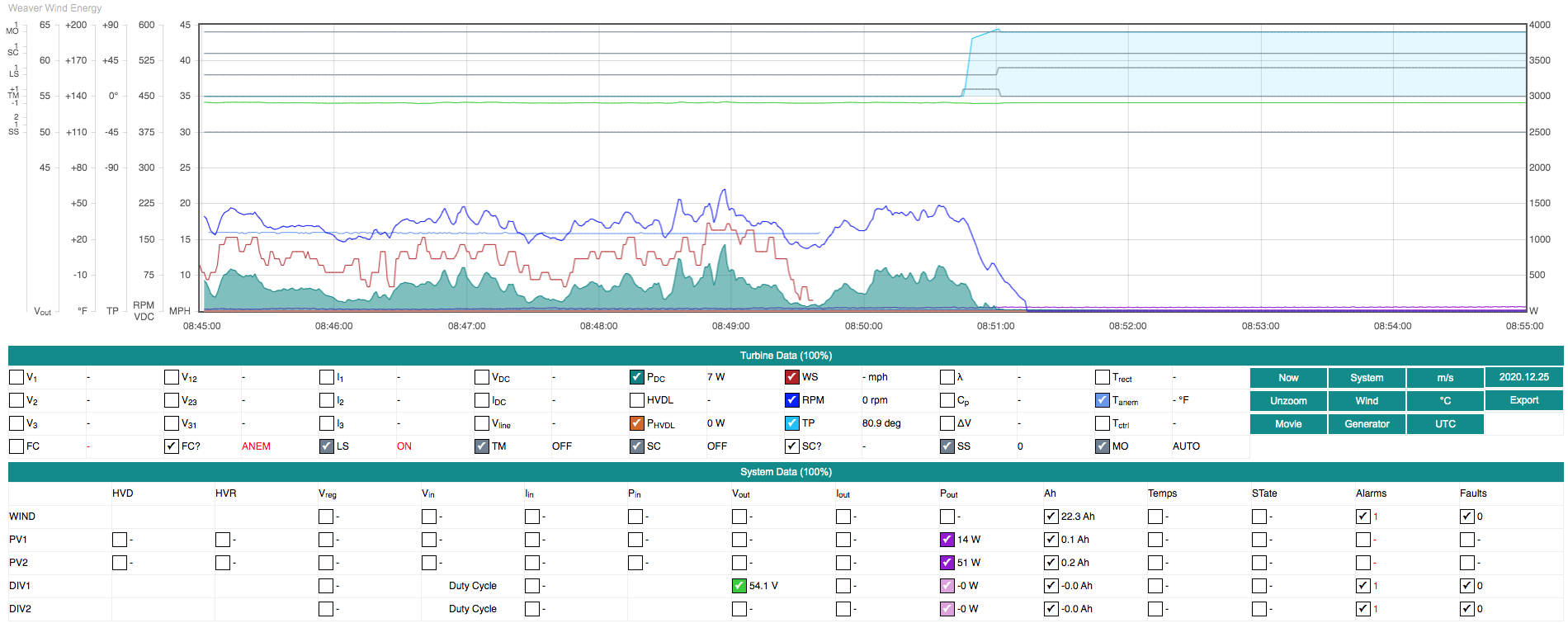
SLIP: This code indicates that tail position is being recalibrated after the equivalent of 10 full rotations (3600 deg) of cumulative tail motion. Small errors in tail position can occur due to stepper motor slippage in high wind conditions.

EXER: This code indicates that the tail mechanism is being exercised (and tail position recalibrated) when no tail motion has been recorded over a 24h period due to light winds.

TAIL: This code indicates that the tail position (TP) has exceeded a maximum limit. This state will always trigger
Shutdown State= 2.
There are three (3) possible turbine shutdown states. All can be set manually on the Controller operating parameters web page, and all may occur automatically during turbine operation. Shutdown states are independent of Turbine operating modes AUTO and MAN.
Shutdown State=0is the normal operating state of the turbine. The W2 turbine controller may automatically set Shutdown State to 1 (e.g., for a remote firmware update) or 2 (e.g., if dangerous operating conditions are detected).Shutdown State=1is a temporary state used for smoothly shutting down the turbine for any reason. It is also the state entered when the system restarts, e.g., after a firmware update. InSS=1the turbine attempts to furl, and engages the shorting contactor only if Controller operating parametersBrake@V,Brake@I, andBrake@RPMare satisfied. Exiting this state requires user input on the Controller operating parameters web page.Shutdown State=2is a permanent state that immediately engages the shorting contactor whether or notBrake@V,Brake@I, and/orBrake@RPMare satisfied. The turbine also attempts to furl. This state can be set manually, but usually occurs only when the controller detects potentially dangerous operating conditions or various system faults. Exiting this state requires operator input on the Controller operating parameters web page, and possibly switching into Manual Mode to recalibrate tail position (see TroubleshootingShutdown State= 2 for further detail).
This section discusses inspection and testing steps that should be done at ground level with access to the open nacelle.
Tail motor operation and tail position calibration
Shorting contactor operation
Tip
Each machine has its own unique personality which probably could be defined as the intuitive sum total of everything you know and feel about it. This personality constantly changes, usually for the worse, but sometimes surprisingly for the better, and it is this personality that is the real object of motorcycle maintenance. The new ones start out as good-looking strangers and, depending on how they are treated, degenerate rapidly into bad-acting grouches or even cripples, or else turn into healthy, good-natured, long-lasting friends. – Robert Pirsig, Zen and the Art of Motorcycle Maintenance (1974)
Slewing drive grease injection.
Blade inspection and touch up.
Anemometer support.
Nacelle wiring inspection.
Bolt torque checks.
These are some of the more common issues we've encountered during field testing of the W2 System.
When SS=2 occurs, the turbine is immediately stopped by electrically shorting its 3-phase AC output through the Shorting contactor and braking resistors in the nacelle. The system will also initiate a full furl.
SS=2 occurs when the controller firmware detects a “failsafe” condition which could be hazardous to persons or equipment if turbine operation were allowed to continue. There are three (3) immediate shutdown thresholds in the Controller operating parameters: Shutdown @V >, Shutdown @I >, and Shutdown @RPM >. If one or more of these is exceeded, SS=2 is set. The most likely cause is extreme gusty wind conditions. Another possibility is turbine “freewheeling” due to unloaded operation which would trigger Shutdown @V >.
Caution
Shutdown State should be reset to 1 or 0 only after determining why a failsafe threshold was exceeded and taking steps to fix the problem.
SS=2 will also occur if an “over-furl” condition is detected, i.e., the stepper motor has driven the tail beyond a point where the Reed switch should have been triggered, but for some reason, was not. The most common reason for this is stepper motor “slippage” due to freeze up or other mechanical failure of the tail drive train. If slippage has occurred, the tail may not have reached the angular limit reported by the System monitor web page and will be found to be in some intermediate position. In this case, Tail position recalibration is required. Reed switch failure is another possible cause.
Caution
The only way to unset SS=2 after an over-furl (reported as FL? = TP in the System monitor web page) is to put the controller into Manual Mode and manually drive the tail (either direction) to trigger the limit switch; doing so will reset tail position. Finally, return the controller to Auto Mode and set Shutdown State to 1 and then to 0 on the Controller operating parameters webpage to restart the turbine. It is always important to try to determine why the problem occurred, but is typically due to tail motor slippage while furling in gusty winds. Slippage does not harm the stepper motor.
Very rarely, the Morningstar wind charge controller may fail to load the turbine resulting in a failsafe shutdown (SS=2) due to over-voltage, but without issuing an alarm or warning message. This has been observed following a 10-min full furl triggered by over-frequency (RPM). The reason why this occurs is unknown. To recover, reset the Morningstar controller by cycling power to it using the "Battery Disconnect" breaker on the TS-MPPT-600V front panel, then set Shutdown State to 1 and then to 0 on the Controller operating parameters webpage.
When HVDL Active has been ON (=1) and is then switched OFF (=0), a furl may be triggered due to a Morningstar wind controller alarm or warning. This is a transient condition which resolves automatically after a short-duration full furl.
Due to a combination of alternator “cogging” and shaft seal friction, the wind speed required for rotor spin-up varies from 12 to 16 mph. Very cold temperatures (affecting shaft seal friction) can require even higher wind speeds for startup. Once rotor speed exceeds about 90 rpm, aerodynamic lift of the blades overcomes stiction and causes a rapid spin-up. After spin-up, when wind speeds fall, the minimum operating wind speed is about 5 mph.
The following is a list of resources about using DocBook – an XML “schema” or “dialect” – to write manuals like this one. Doing this requires a text editor like emacs that can do XML validation (nxml-mode), and then using XSL stylesheet(s) and CSS with xsltproc to convert DocBook XML to HTML and (potentially) PDF. It took more effort than I originally imagined to make all this work, but the result is a well-organized, validated XML document that can be used to generate nice looking HTML.
-
These are the files used to produce this document:
There's a bunch of processing software needed too, all of which is described in
w2_system_manual.xml. -
DocBook 5.2: The Definitive Guide – Describes all the XML tags that can be used in a DocBook document.
-
DocBook XSL: The Complete Guide – All about using XSL stylesheets with XML docs. Includes information about xsltproc, incorporating CSS, and creating custom extensions to XSL stylesheets.
-
DocBook Wiki – Found links to DocBook CSS files here including a FreeBSD CSS stylesheet, docbook.css, that was used (with further modifications) to style the HTML.
-
Emacs Wiki - Using Nxml Mode with DocBook – Scroll down to "Docbook 5.x". After drowning in web documentation with too much detail and mostly relevant to DocBook 4.5 and older, this wiki entry was KEY to getting everything working with DocBook 5.x using emacs and xsltproc.
-
The DoCookBook: Recipes for DocBook Developers.
-
An introduction to DocBook, a flexible markup language worth learning
